

This Texas Star DX500V turned into a rabbit hole. Partly my fault.
I should turn down jobs that have this quality of repair visible inside.
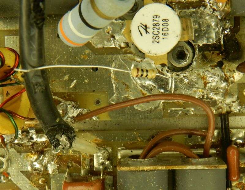
Normally seeing the 10-ohm base resistors with lead wire this long should have prompted me to just put the cover back on. But the owner is an old friend who just likes to try his hand.
He replaced all 4 RF transistors. With legitimate HG parts.
He thinks. More on that later.
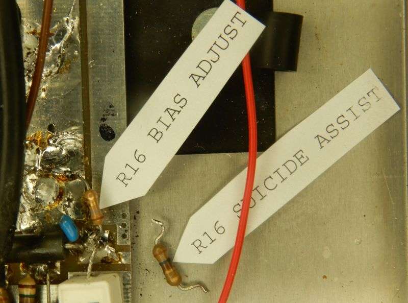
But first, what he failed to put right before trying out the new 2879s. The previous set of 10-ohm resistors had smoked. But R16 is in parallel with them. Since the value of 16 is typically under 2 ohms, it will suffer rapidly when a 2879 breaks down inside.
R16 controls the bias current, or zero-drive current for the front two 2879s. The higher the resistance, the higher the transistors' base and collector current. This one was blown open. This is what caused the amplifier to shut down the power supply. An open R16 will cause the 2879s to draw all the current you can provide. Turns out this popped the front two 2879s.
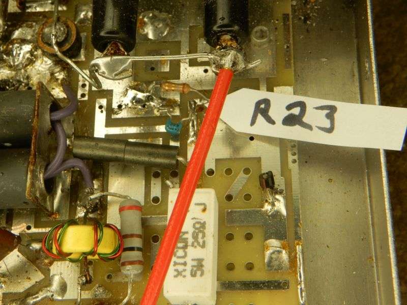
R23 controls bias for the rear pair. It was open, too. A new 1.8 ohms is what you see here.
I bought the replacement transistors from ICA in Jersey. The customer claims he did, as well.
But what's wrong with this picture? One of these things is not like the other.
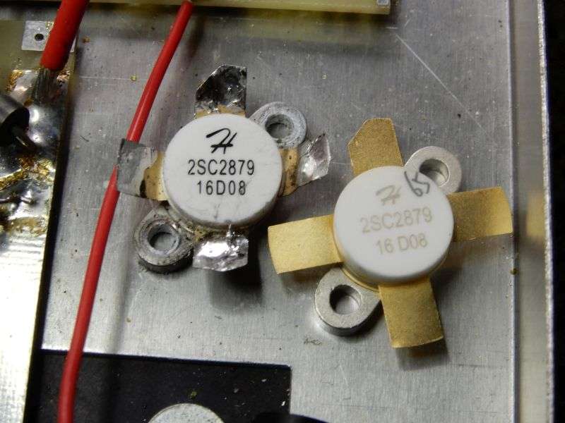
The ones with the lighter ink and the hfe number penciled in are the ones I bought. The darker ink is on the customer's blown parts. Baffles me.
So now it's time to check the zero-signal idle current for the front pair. The wire jumper with two ferrite beads feeds power to the collector circuit. Unsoldering it from the outer-edge foil trace permits you to insert a current meter. I set mine to the 20-Amp scale, just to avoid surprises.
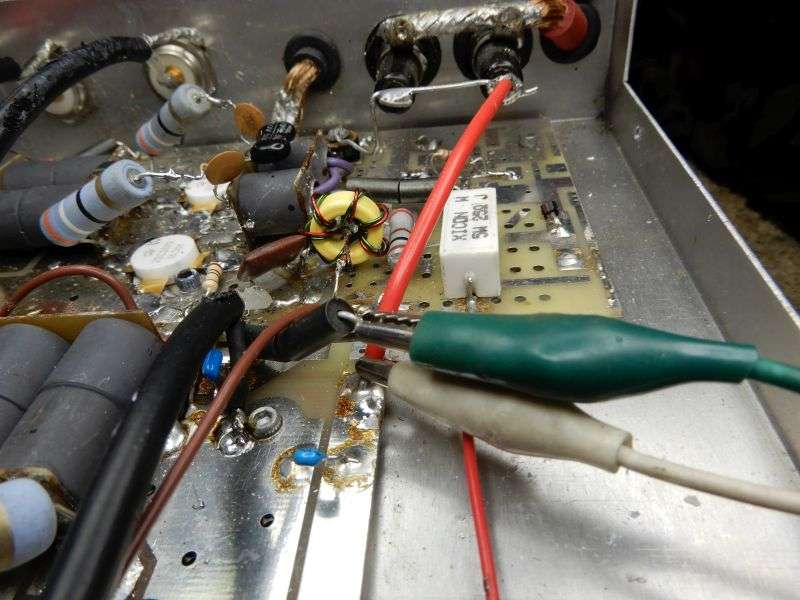
My target range is 150 to 250 mA with the relay keyed and no drive. No trimpot to twist here.
Here's the same accidental test point for the rear pair.
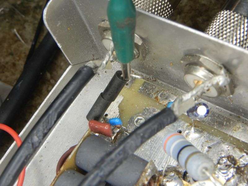
The jumper wire is not in a circuit-board hole. It's just butt-soldered to the outer foil trace. Sounds sketchy, but seems to work okay.
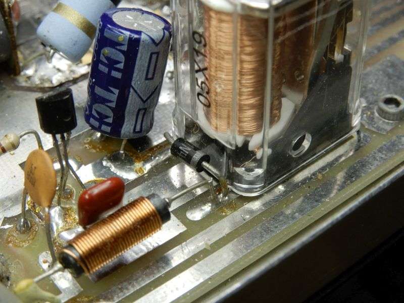
To key the relay without a radio, first make sure you have the dummy load connected. Next touch a gator clip to the anode, the NOT banded end of this diode just to the rear of the relay.
This is the sort of thing that makes a job like this sketchy. The last half-dozen guys who replaced the swamping resistors on the output combiner. This one was in need of rewinding, but I wasn't feeling that patient this day.
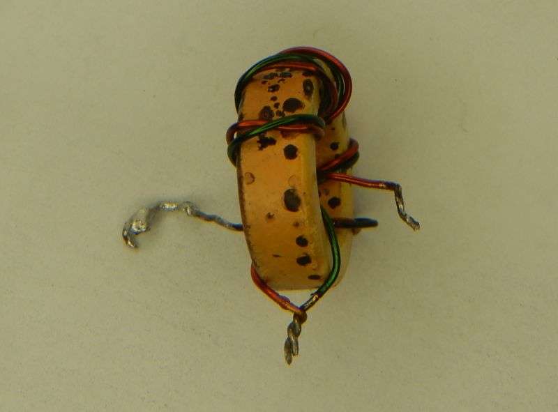
Fortunately I had a new one on hand. Winding these is not my favorite pastime.
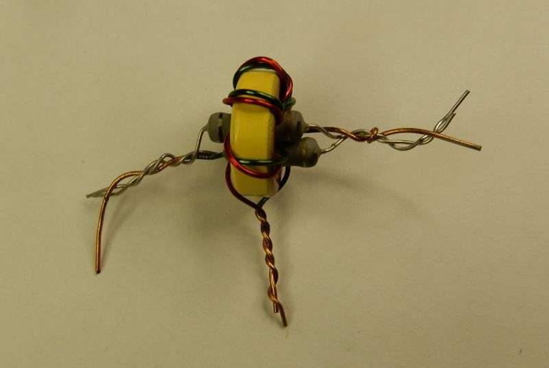
This way the lead wires all reach where they need to.
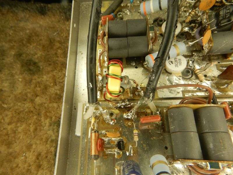
Now that you have a zero-drive current reading for each pair of transistors, what if the reading is too high? Simple solution is parallel another resistor across R16 or R23. This one had the 1.8 ohm R16 paralleled with a 22 ohm. I tried 10 ohms at first, but it cut the bias current too low. YMMV
The sharp-eyed reader will notice that the customer's 2879s with the dark ink were tried first. I checked the front pair, and they had survived. Didn't follow through and isolate the base lead from each of the rear pair. Burned the combiner's swamping resistors. The front pair were working, but the rear pair were dead. Oops. Shoulda checked.
But I wasn't brave enough to replace only the rear pair. Didn't imagine they would accidentally match the new ones from my stock. All four 2879s got changed, all with matching hfe numbers.
A 22 ohm in parallel with the 1.8 ohm R23 sets proper zero-drive bias current for the back pair.
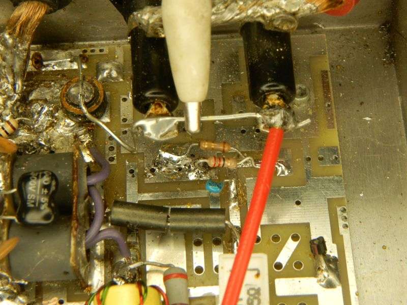
The same trick worked for the front pair at R16. One advantage of a matched set of four.
All this work and it only gets me 300 Watts PEP with 20 Watts peak drive. But at least it's not broke no mo.
73
I should turn down jobs that have this quality of repair visible inside.
Normally seeing the 10-ohm base resistors with lead wire this long should have prompted me to just put the cover back on. But the owner is an old friend who just likes to try his hand.
He replaced all 4 RF transistors. With legitimate HG parts.
He thinks. More on that later.
But first, what he failed to put right before trying out the new 2879s. The previous set of 10-ohm resistors had smoked. But R16 is in parallel with them. Since the value of 16 is typically under 2 ohms, it will suffer rapidly when a 2879 breaks down inside.
R16 controls the bias current, or zero-drive current for the front two 2879s. The higher the resistance, the higher the transistors' base and collector current. This one was blown open. This is what caused the amplifier to shut down the power supply. An open R16 will cause the 2879s to draw all the current you can provide. Turns out this popped the front two 2879s.
R23 controls bias for the rear pair. It was open, too. A new 1.8 ohms is what you see here.
I bought the replacement transistors from ICA in Jersey. The customer claims he did, as well.
But what's wrong with this picture? One of these things is not like the other.
The ones with the lighter ink and the hfe number penciled in are the ones I bought. The darker ink is on the customer's blown parts. Baffles me.
So now it's time to check the zero-signal idle current for the front pair. The wire jumper with two ferrite beads feeds power to the collector circuit. Unsoldering it from the outer-edge foil trace permits you to insert a current meter. I set mine to the 20-Amp scale, just to avoid surprises.
My target range is 150 to 250 mA with the relay keyed and no drive. No trimpot to twist here.
Here's the same accidental test point for the rear pair.
The jumper wire is not in a circuit-board hole. It's just butt-soldered to the outer foil trace. Sounds sketchy, but seems to work okay.
To key the relay without a radio, first make sure you have the dummy load connected. Next touch a gator clip to the anode, the NOT banded end of this diode just to the rear of the relay.
This is the sort of thing that makes a job like this sketchy. The last half-dozen guys who replaced the swamping resistors on the output combiner. This one was in need of rewinding, but I wasn't feeling that patient this day.
Fortunately I had a new one on hand. Winding these is not my favorite pastime.
This way the lead wires all reach where they need to.
Now that you have a zero-drive current reading for each pair of transistors, what if the reading is too high? Simple solution is parallel another resistor across R16 or R23. This one had the 1.8 ohm R16 paralleled with a 22 ohm. I tried 10 ohms at first, but it cut the bias current too low. YMMV
The sharp-eyed reader will notice that the customer's 2879s with the dark ink were tried first. I checked the front pair, and they had survived. Didn't follow through and isolate the base lead from each of the rear pair. Burned the combiner's swamping resistors. The front pair were working, but the rear pair were dead. Oops. Shoulda checked.
But I wasn't brave enough to replace only the rear pair. Didn't imagine they would accidentally match the new ones from my stock. All four 2879s got changed, all with matching hfe numbers.
A 22 ohm in parallel with the 1.8 ohm R23 sets proper zero-drive bias current for the back pair.
The same trick worked for the front pair at R16. One advantage of a matched set of four.
All this work and it only gets me 300 Watts PEP with 20 Watts peak drive. But at least it's not broke no mo.
73


