Hey, Ranch 55 do you happen to sell any parts for Texas Stars, I could use a board for another one I have that is a twelve guage as it had #3 board missing when I got it .Yeah, they probably were bad.
Alway, always, when replacing the power transistors, always replace the 10 ohm and the 1.6 ohm bias resistors.....They can be bad even without looking burnt.
It is cheap insurance to help protect the transistors.

You are using an out of date browser. It may not display this or other websites correctly.
You should upgrade or use an alternative browser.
You should upgrade or use an alternative browser.
-
You can now help support WorldwideDX when you shop on Amazon at no additional cost to you! Simply follow this Shop on Amazon link first and a portion of any purchase is sent to WorldwideDX to help with site costs.
-
A Winner has been chosen for the 2026 July 4th Retevis RA89R Giveaway! Click Here to see who won!
Texas Star Sweet Sixteen restoration questions and suggestions please
- Thread starter Danzik
- Start date

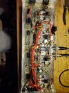
Ok, I tried it out tonight , it keys but had no power output and I noticed where someone had disconnected the wire on the relay that goes to the input splitters on #8 on the relay. Now I am somewhat confused by the color schematic I have that shows how it actually goes does anyone have a photo perhaps? The color diagram show a wire coming off of #8 and going straight to ground and we know that's not right, so is it supposed to be a 120 pf disc capacitor with one end going to ground by the emitter and then the other end of the capacitor soldered to the wire coming from pin #8 on the relay then both those get soldered to the trace leading to the splitter???? Thanks
Attachments
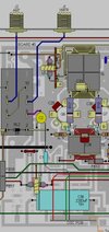
Zoom in on the relay area.....
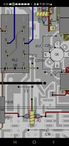
The colored diagram you show above is not the correct one to look at. That is for the amplifier with the old oscillator board installed. The second diagram is the correct one.......
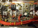
As I mentioned before, there are many parts missing that have been removed in the photos you originally posted. I doubt you have found and replaced all of them......

The colored diagram you show above is not the correct one to look at. That is for the amplifier with the old oscillator board installed. The second diagram is the correct one.......
As I mentioned before, there are many parts missing that have been removed in the photos you originally posted. I doubt you have found and replaced all of them......
Last edited:
10-4 Ranch55, yeah I did try it the way yours is last night but not with near as large of a capacitor so not sure if that may be my issue. It would only dead key about 2 more watts then my radio and with any modulation it would swing backwards! I will try a larger disc capacitor later today and get back with the results. If I am missing any parts I sure would not know what it would be but I will take current photos when I get home from work and possibly you may be able to spot somthing wrong. Thanks very much for your help I appreciate it !Zoom in on the relay area.....
The colored diagram you show above is not the correct one to look at. That is for the amplifier with the old oscillator board installed. The second diagram is the correct one.......
As I mentioned before, there are many parts missing that have been removed in the photos you originally posted. I doubt you have found and replaced all of them......
View attachment 72544
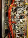
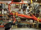
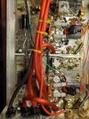
Now, the red power wires going to the output transformers is just a current upgrade correct?Zoom in on the relay area.....
The colored diagram you show above is not the correct one to look at. That is for the amplifier with the old oscillator board installed. The second diagram is the correct one.......
As I mentioned before, there are many parts missing that have been removed in the photos you originally posted. I doubt you have found and replaced all of them......
View attachment 72544

Yes, along with the added solder on top of the power traces to bolster them.Now, the red power wires going to the output transformers is just a current upgrade correct? View attachment 72545
Above is the input "bandpass" filter capacitor that is missing in your amplifier.....
This is the input tuning capacitor above, tuned for lowest VSWR on the input from radio into amplifier......
View attachment 72548
Above is the input "bandpass" filter capacitor that is missing in your amplifier.....
View attachment 72549
View attachment 72550
This is the input tuning capacitor above, tuned for lowest VSWR on the input from radio into amplifier......
View attachment 72551
View attachment 72552
View attachment 72553
Attachments
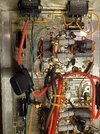

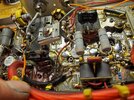

I moved and set the adjustable cap to 130pf and put it down where your 130pf mica is, I may just leave the tuner there for a input tune, I may have to wait till the 2200pf cap comes in as I don't have one on hand, I tried one that was 2725pf but the amp really isn't working properly still, if you see anything improper in the photos that would cause issues please let me know, thanksView attachment 72548
Above is the input "bandpass" filter capacitor that is missing in your amplifier.....
View attachment 72549
View attachment 72550
This is the input tuning capacitor above, tuned for lowest VSWR on the input from radio into amplifier......
View attachment 72551
View attachment 72552
View attachment 72553
dxChat
- No one is chatting at the moment.
