
You are using an out of date browser. It may not display this or other websites correctly.
You should upgrade or use an alternative browser.
You should upgrade or use an alternative browser.
-
You can now help support WorldwideDX when you shop on Amazon at no additional cost to you! Simply follow this Shop on Amazon link first and a portion of any purchase is sent to WorldwideDX to help with site costs.
-
A Winner has been chosen for the 2026 July 4th Retevis RA89R Giveaway! Click Here to see who won!
The EF vs dipole Full Wave pattern anomoly
- Thread starter TheBlaster
- Start date

On second read it starts to stick, I will need a 3rd and fourth read and I do understand the principle of the areas of cancellation and reinforcement thus the EF FW - DX disaster pattern.
I did start to think electric and magnetic fields relationship (as opposed to the V and I centers) i.e. RF but did not want to jump the gun as I could not recall their precise relationships. I will have to look at a diagram. It is a complex jigsaw.
I will have a pure guess about the 5/8 as I am aware the far field ground reflection is critical to get the gain or reinforcement at a lower angle... I am going to guess that the ground reflection VF somehow changes the phase of the out of phase portion and means it then becomes in phase at pseudo Brewster related angles... pulling down what would have been in a 1/2 wave EF by a few degrees.
The statement above could be totally wrong, I am expecting to see poor pattern for a 5/8 in space") probably significantly worse than a 1/2 wave. I will try and find out in due course.
probably significantly worse than a 1/2 wave. I will try and find out in due course.
I did not take in the phase depictions yet from your models. need to let the other bit sink in first.
I did start to think electric and magnetic fields relationship (as opposed to the V and I centers) i.e. RF but did not want to jump the gun as I could not recall their precise relationships. I will have to look at a diagram. It is a complex jigsaw.
I will have a pure guess about the 5/8 as I am aware the far field ground reflection is critical to get the gain or reinforcement at a lower angle... I am going to guess that the ground reflection VF somehow changes the phase of the out of phase portion and means it then becomes in phase at pseudo Brewster related angles... pulling down what would have been in a 1/2 wave EF by a few degrees.
The statement above could be totally wrong, I am expecting to see poor pattern for a 5/8 in space
probably significantly worse than a 1/2 wave. I will try and find out in due course.I did not take in the phase depictions yet from your models. need to let the other bit sink in first.
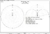
Here we go... the 1/2 wave in free space has max gain at 8 degrees and identical gain down to 0 degrees, 2.0dBi is suggested. The 5/8 wave peaks 14 degrees...1.8dBi
This is not what I was anticipating. I imagines a 5/8 shooting RF off at a cloud warming angle without ground below.
I imagine this is to prove a concept ? As this has no use in our reality.
This is not what I was anticipating. I imagines a 5/8 shooting RF off at a cloud warming angle without ground below.
I imagine this is to prove a concept ? As this has no use in our reality.
Attachments

I guess the green infill lines are just shading as opposed to representing anything specific. I can see the difference of the phase info between the 2 antennas... however
what still confuses me in the shading is that there looks to be just 1 sine wave depicted in the EFFW and I cannot seem to understand how that cancels itself.
I am probably misinterpreting how phase is represented in modelling software. I have also only ever encountered phase cancellation when 2 waves exist not 1. This is the fundamental problem for me in a barrier to understanding.
I think there is a conceptual disconnect with how these waves of V and I are traveling in a wire with respect to the shape of a sine wave and their 3D omnidirectional existence in space outside the antenna.
At the moment the best I can do is imagining a current centre (in fact 2 for a FW dipole) emerging from the voltage gif of the 1/2 wave or extending the truncated red voltage waves to complete another 1/4 cycle at the ends.. you need to add https to the start of this link as I cannot get the forum to display it...
://i.stack.imgur.com/S2NUM.gif
Knowing current centre would be like a banana bendy line flipping one side then the other side with peak at feed point - and adding secondary dipole (making a full wave) having a current centre on the other side of the second dipole compared to the first.
That kind of makes sense for a full wave dipole it looks like just 1 sine fitting in the FW length of the FW dipole - not competing with anything. Other than matching and very unhelpful dimensions for many frequencies, practically it seems to be a fine radiator. The pattern can even be classed good when vertical.
The out of phase issue for a EFFW I am very much struggling with. I just cannot seem to square the circle of there being 1 wave introduced into a transducer (the EFFW element) and there being 2 waves cancelling other out in places.
I think it is the 2D into 3D that is awkward. Wire being 3D yes but mainly just a thin wire up and down vertically.. and then imagining waves coming out of that are invisible is very much a stretch of the imagination ! We have the electric and magnetic fields at right angles to each other so I can visualize and even see that in a 3D depiction in ARRL book but imagining that going off in all directions from an omnidirectional antenna is hard work for the mind.
Last edited:
Something I notice is that the sine wave on the gif only goes 1/2 way up each 1/4 wave element when volts peak at the ends of the dipole... so with a full wave maybe the component that cancels is somehow in the second 1/4 of each element. I am totally clutching at straws now though.
I can understand there are 2 current centres of opposing polarity but they are not out of phase as out of phase implies 2 separate sine waves with a 180 degree phase shift.
They are opposing polarities of the same single sine wave. I would have thought.
They are opposing polarities of the same single sine wave. I would have thought.
I think there will have to be an acceptance of this out of phase radiation being represented in this way (despite it being part of one and the same sine wave). It seems to be just how modelling software does it. Here is a 5/8 wave animated GIF showing the out of phase portion of a 5/8 wave. Although I am still not entirely sure why the currents are so different for a EF FW vs the FW dipole other than accepting as a fact that with a centre feed, currents are always in phase.
Keep your eye on the red parts developing that is easiest. The only other way I can view this is that the main current centre develops 2 x 180 degree arcs thus producing a 360 degree cycle of RF. In addition (or in fact subtraction) the lower developing current centre colour coding suggests it is a developing opposition despite its relatively small size.
Seemingly for a EFFW this is much more serious subtraction and therefore causes great attenuation at some angles. Whereas the principle of operation for a 5/8 is to flatten the pattern in conjunction with far field ground reflections. Feel free to pick holes, these are just entertaining musings and ways of trying to take it in for myself, rather than presentation of facts.
check out page 113 with regard to the current distribution in both 1/2 wl. & full wl. (dipole) antennas, figures 3.2-8(a), 3.2-8(b) and page 114; 3.2-9 & 3.2-10.
https://ocw.mit.edu/courses/electri...s-and-signals-spring-2003/readings/ch3new.pdf
https://ocw.mit.edu/courses/electri...s-and-signals-spring-2003/readings/ch3new.pdf
Last edited:
I know its been a while, sorry, I've just been very busy and my long responses can take some time.
The current is 100% responsible for all radiation from an antenna. If the voltage contributed to radiation, the modeling programs would also show the voltage.
Odd, every time I do this, the half wavelength and below all have peak gain at 0 degrees, and the 5/8 has peak gain at about 5 degrees. As you go past that half wavelength point the angle starts to increase, and continues to do so as you add length, at least to a point. I may have to load up mmana-gal again and see if your results also happen for me...
In the 4nec2 software, the green infill lines are only used as an indicator of phase. If you don't include the phase, the current will be shown as magnitude, such as with my models that don't include the phase and the models you posted.
So, as we know with the sign wave and currents, the part that is shown on one side of the line (antenna model in this case) represents being positive and the part that is shown on the other side of the line represents being negative. So time for a thought experiment.
Take a nail and wrap it with a length of wire, all in the same direction, add a battery, and viola we now have an electromagnet. Now take that same wire and wrap it around the same nail again, except this time the first half in one direction and the second half in the reverse direction. What happens? Why? This is essentially what is happening with the currents in the antenna as, say, in a half wavelength end fed antenna all the currents are flowing in one direction while in a full wavelength end fed antenna half of the currents are flowing in each direction.
This quote should also include that picture. Yea I can't get it to show either. I suppose I could put it in my album and post it from there if we really need to.
I'm going to add in a quote from later here as well
Yes, the V and I waves are 90 degrees out of phase with each other. In this case the current creates a sine wave and the voltage creates a co-sine wave. As I said above, the voltage doesn't cause radiation. If it did the modeling programs we use, which does in fact calculate the voltage, would also show it in its output data.
It all comes down to the relationship between voltage and current, and while its not listed here, resistance/impedance also plays its part. This is actually not an easy thing to explain.
So lets try and explain the difference between the three.
Voltage, what is it. Lets look at a battery. You have a voltage difference between the two terminals (unless the battery is dead). This difference exists weather or not the battery is even being used. This is not the "work" itself, but the energy behind the work, or the potential for work. It exists weather or not the work is being done or not.
Next we have resistance (impedance). This is easy to explain as this resists the amount of work being done.
Finally we have the current. This is the actual work that is done. How much work gets done? That depends on the voltage and resistance (impedance).
So to explain why the voltage curve is not shown in modeling software, the voltage is the potential for work, not the work itself. The current represents the work, or in the case of an antenna the radiation itself.
I hope this explains part of it for you.
From another point of view, a car can have potential of 500 or more horsepower, but you the driver aren't bringing out all of that power all of the time. You use the accelerator to restrict (read resist or impede) the flow of air and fuel into the engine, and thus use the engine at a lower amount of horsepower.
The DB
I did start to think electric and magnetic fields relationship (as opposed to the V and I centers) i.e. RF but did not want to jump the gun as I could not recall their precise relationships. I will have to look at a diagram. It is a complex jigsaw.
The current is 100% responsible for all radiation from an antenna. If the voltage contributed to radiation, the modeling programs would also show the voltage.
Here we go... the 1/2 wave in free space has max gain at 8 degrees and identical gain down to 0 degrees, 2.0dBi is suggested. The 5/8 wave peaks 14 degrees...1.8dBi
This is not what I was anticipating. I imagines a 5/8 shooting RF off at a cloud warming angle without ground below.
I imagine this is to prove a concept ? As this has no use in our reality.
Odd, every time I do this, the half wavelength and below all have peak gain at 0 degrees, and the 5/8 has peak gain at about 5 degrees. As you go past that half wavelength point the angle starts to increase, and continues to do so as you add length, at least to a point. I may have to load up mmana-gal again and see if your results also happen for me...
guess the green infill lines are just shading as opposed to representing anything specific.
In the 4nec2 software, the green infill lines are only used as an indicator of phase. If you don't include the phase, the current will be shown as magnitude, such as with my models that don't include the phase and the models you posted.
however
what still confuses me in the shading is that there looks to be just 1 sine wave depicted in the EFFW and I cannot seem to understand how that cancels itself.
So, as we know with the sign wave and currents, the part that is shown on one side of the line (antenna model in this case) represents being positive and the part that is shown on the other side of the line represents being negative. So time for a thought experiment.
Take a nail and wrap it with a length of wire, all in the same direction, add a battery, and viola we now have an electromagnet. Now take that same wire and wrap it around the same nail again, except this time the first half in one direction and the second half in the reverse direction. What happens? Why? This is essentially what is happening with the currents in the antenna as, say, in a half wavelength end fed antenna all the currents are flowing in one direction while in a full wavelength end fed antenna half of the currents are flowing in each direction.
I think there is a conceptual disconnect with how these waves of V and I are traveling in a wire with respect to the shape of a sine wave and their 3D omnidirectional existence in space outside the antenna.
At the moment the best I can do is imagining a current centre (in fact 2 for a FW dipole) emerging from the voltage gif of the 1/2 wave or extending the truncated red voltage waves to complete another 1/4 cycle at the ends.. you need to add https to the start of this link as I cannot get the forum to display it.
This quote should also include that picture. Yea I can't get it to show either. I suppose I could put it in my album and post it from there if we really need to.
I'm going to add in a quote from later here as well
The out of phase issue for a EFFW I am very much struggling with. I just cannot seem to square the circle of there being 1 wave introduced into a transducer (the EFFW element) and there being 2 waves cancelling other out in places.
Yes, the V and I waves are 90 degrees out of phase with each other. In this case the current creates a sine wave and the voltage creates a co-sine wave. As I said above, the voltage doesn't cause radiation. If it did the modeling programs we use, which does in fact calculate the voltage, would also show it in its output data.
It all comes down to the relationship between voltage and current, and while its not listed here, resistance/impedance also plays its part. This is actually not an easy thing to explain.
So lets try and explain the difference between the three.
Voltage, what is it. Lets look at a battery. You have a voltage difference between the two terminals (unless the battery is dead). This difference exists weather or not the battery is even being used. This is not the "work" itself, but the energy behind the work, or the potential for work. It exists weather or not the work is being done or not.
Next we have resistance (impedance). This is easy to explain as this resists the amount of work being done.
Finally we have the current. This is the actual work that is done. How much work gets done? That depends on the voltage and resistance (impedance).
So to explain why the voltage curve is not shown in modeling software, the voltage is the potential for work, not the work itself. The current represents the work, or in the case of an antenna the radiation itself.
I hope this explains part of it for you.
From another point of view, a car can have potential of 500 or more horsepower, but you the driver aren't bringing out all of that power all of the time. You use the accelerator to restrict (read resist or impede) the flow of air and fuel into the engine, and thus use the engine at a lower amount of horsepower.
The DB
"The current is 100% responsible for all radiation from an antenna. If the voltage contributed to radiation, the modeling programs would also show the voltage."
this statement is patently absurd and makes a false assumption based on the limitation of an antenna modeling software program. in the total absence of any driving voltage there is no current. both need to be present for any transverse electromagnetic radiation to take place.

the voltage present is represented by the electric e-field.
the current present is represented by the magnetic h-field.
the radiation pattern is that of a vertically polarized radiator..
the plane of the electric e-field always denotes polarization.
capacitance depends on voltage.
polarization depends on voltage.
impedance depends on voltage.
time phase depends on voltage.
radiation depends on voltage.
this statement is patently absurd and makes a false assumption based on the limitation of an antenna modeling software program. in the total absence of any driving voltage there is no current. both need to be present for any transverse electromagnetic radiation to take place.
the voltage present is represented by the electric e-field.
the current present is represented by the magnetic h-field.
the radiation pattern is that of a vertically polarized radiator..
the plane of the electric e-field always denotes polarization.
capacitance depends on voltage.
polarization depends on voltage.
impedance depends on voltage.
time phase depends on voltage.
radiation depends on voltage.
Last edited:
I must say I did think current cannot exist without volts so it seems they are interdependent for either to exist. I think The DB basically meant for the purpose of antennas current centre's seem generally to be given greater weight than voltage in any kind of imagery and seemingly that includes modelling.
Models are fun and enjoyable but they are merely presenting a best case scenario for some uniform ground type many multiple wavelengths from your antenna without obstacles and in reality per band you are never working in a best case scenario..... it is quite uncommon that anyone uses an antenna on uniform ground without obstructions close by or concreting of earth nearby. You could experience very different results at the QTH from any given model. It is just an idealized approximation.
They are far from gospel, they are not antennas at QTH's. To make hard and fast performance statements about an antenna model is precisely that, about a model, not reality.
Last edited:
with regard to all antenna modeling software, even with their shortcomings and the "work arounds" required to minimize their limitations, the validity of the output data is only as dependable as the accuracy of the user inputted data and information, the combination of all of the above explaining why multiple users can model the same antenna design and yield noticeably different results, attesting to the apparent lack of conformity among multiple program runs.
see how many different patterns you can find for a j-pole antenna.
https://duckduckgo.com/?q=j-pole+antenna+radiation+pattern&t=h_&iax=images&ia=images
see how many different patterns you can find for a j-pole antenna.
https://duckduckgo.com/?q=j-pole+antenna+radiation+pattern&t=h_&iax=images&ia=images
this statement is patently absurd and makes a false assumption based on the limitation of an antenna modeling software program.
As said from someone who has demonstrated multiple times that he doesn't actually understand how antenna modeling software actually works.
in the total absence of any driving voltage there is no current. both need to be present for any transverse electromagnetic radiation to take place.
If you bothered to read the entirety of the post you quoted from, you would see that I not only understand this, but I actually spoke to this. That being said, the voltage itself, and by extension the e-field that it creates, does not contribute to an antennas radiation directly. It is the current that the voltage induces, as I explained in detail in said post that you quoted, and by extension the h field that all of the radiation comes from.
Perhaps instead of looking for one line to take out of context you should try reading the entire post to put it all in perspective, but then, you do this quite often so I have come to expect it from you.
Also, you might actually try learning how to use the actual quote system that this forum uses. It really isn't that hard to figure out, hell, first time users have no problem figuring it out all the time. If they can figure it out, someone who has a link in their signature to a facebook page that claimes to be a professional...
the voltage present is represented by the electric e-field.
Yes, I know this. Your point?
the current present is represented by the magnetic h-field.
Yes, I know this. Your point?
the radiation pattern is that of a vertically polarized radiator..
This picture is used to show the e- and h-fields as an AC signal travels down a wire, not through space. When it comes to demonstrating what is happening in space, while this can be said to be a representation, it is a very poor representation at best. Its simply bad at what is actually happening in a 3d environment.
And... It is also irrelevant to what I said.
capacitance depends on voltage.
Yes, I know this, and it is not relevant to what I was saying.
polarization depends on voltage.
We call an antenna vertically polarized because it has a physical vertical dimension. The fact that the e-field happens to line up to the physical direction of the antenna is incidental.
impedance depends on voltage.
Yes, I know this, and it is not relevant to what I was saying.
time phase depends on voltage.
Wait, time phase? That is a new line out of you. And you are using it wrong... Go figure.
radiation depends on voltage.
The voltage distribution on the antenna does not contribute to radiation, however, as I said in the same post you apparently didn't bother to read, the voltage induces the current, which creates the h-field, and that is where the radiation comes from. Actually, not all current is induced by voltage, but talking about parasitic elements and how they function is a bit much for you so I won't waste either of our time.
So, again, one last time, Yes, I know this, and it is not relevant to what I was saying.
Man, you really are bad at getting things in context...
Now that that is done, I have a question for you.
So you said I made an assumption based on the...
limitation of an antenna modeling software program.
So, Mr Self Proclaimed Expert, what exactly is this limitation you speak of?
I think The DB basically meant for the purpose of antennas current centre's seem generally to be given greater weight than voltage in any kind of imagery and seemingly that includes modelling.
Bingo.
Models are fun and enjoyable but they are merely presenting a best case scenario for some uniform ground type many multiple wavelengths from your antenna without obstacles and in reality per band you are never working in a best case scenario..... it is quite uncommon that anyone uses an antenna on uniform ground without obstructions close by or concreting of earth nearby. You could experience very different results at the QTH from any given model. It is just an idealized approximation.
Yes and no.
If, for example, you are on a five degree hill that is flat at five degrees for a significant length in all directions from the antenna, then a ground mounted antenna, and an antenna that is mounted not to far above said ground, their radiation patterns will be very close to five degrees off. The downhill side will be five degrees lower and the uphill side will be five degrees higher.
If you have an antenna that is mounted, lets say 200 feet above the earth, and you are above a flat plain, your antenna's angle of radiation will actually be lower than shown in the model as the earth itself curves down away from the antenna.
A lot of people look at antenna models for an antenna mounted next to a mountain, and then assume that one that shows a higher angle of radiation will work better, but this is not necessarily true. The antenna's angle of radiation in the direction of said mountain will always be above the peak of said mountain as the side of the mountain becomes the earth that determines part of the radiation pattern.
Something you at least began to notice, when mounted over an earth, any antenna's radiation pattern as determined by said antenna model, is determined in part by the layout and quality of said earth. Because of this, a person who is experienced with working with both antenna models and real world installations can make certain determinations that are very accurate.
Also, there is a web site out there (or was it a program) that uses topography data to show where your local signal is stronger and weaker based on where your antenna is. Its been a while (years) since I played with it, but it is a thing. Perhaps someone else happens to know what it was called?
Edit: I didn't find the one I was looking for, but there is also VOACAP (or Voice of America Coverage Analysis Program), which I haven't personally used, but it is a very similar program in some ways.
And antenna programs were never meant to be treated as gospel, proper use of said programs requires understanding what they are telling you and putting it in perspective of the world around the antenna. Sometimes that is easier said than done, but in others it is far easier.
TheBlaster, as you have shown that you can think things through, based on what I did a few posts ago I have a question for you. I asked you to model and compare two antenna's in free-space. Why do you think I would do that when a lot of people think free-space modeling is irrelevant? What, in your opinion, are free-space models showing you that models over an earth don't?
The DB
Last edited:
dxChat
- No one is chatting at the moment.