• You can now help support WorldwideDX when you shop on Amazon at no additional cost to you! Simply follow this Shop on Amazon link first and a portion of any purchase is sent to WorldwideDX to help with site costs.

The loudest AM "CB" chassis ever? EPT3000-10A

loosecannon

Sr. Member
Mar 9, 2006
4,419
4,073
273
Hi all,

A couple of years ago i was gifted a radio by a very nice forum member who thought i might be interested in restoring/repairing it.

First i would like to say a big THANK YOU!!! to the forum member who gave this radio in hopes that i would dig into it someday. It's up to you if you want to reveal yourself, but i am finally getting around to it.

he told me it was unlike any other "export" chassis he had seen. i had my doubts :)

well, when i got the radio i had to admit he was right because i had never seen this chassis before.

yes, it's a Ranger board, and yes, it is definitely a pre-cursor to the EPT3600 series boards.

BUT! this chassis had something that i had never seen before.

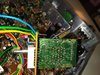
this board has two separate TDA2003 audio amps that take the modulated audio from the PNP modulator stage, amplifies it (push pull im guessing?), and then feeds it through a massive transformer before delivering it to the driver and final.

To me, it seems like this would make for some SERIOUS AM modulation which im guessing was it's intended purpose.

I am in the process of re-capping and repairing this radio right now so i can't speak to how it sounds or what kind of PEP ill get out of it, but it is only a single final radio, so im guessing no more than 30 watts PEP or so.

there are a couple of cap values i'll be upping, and i am also going to upgrade one of the PNP modulator transistors, but that's it so far.

the only pics i have are of a couple of hacks im fixing, but more will be coming soon.

here is the schematic, or as close as ive found (my audio chip is not a TA7222):
http://www.cbtricks.com/radios/rci/ss_33/graphics/ranger_ss33_sch.pdf

there really isn't any info about this radio out there, but comparing it to an EPT3600 board shows that it's basically the same thing except for the modulation sections.

one question about the schematic. specifically the lower right corner where the power enters the radio.
look at TR38, TR39, and TR40. WTF?!

these do not exist in my radio and i think it's a typo because of it's similarity to the modulator section.
what say you all?

20180803_001639.jpg

20180803_013650.jpg

more pics and info to come.
LC
 

Attachments

  • 20180803_001653.jpg
    20180803_001653.jpg
    1.7 MB · Views: 5

sorry,

it says SS3000 on the front, but i don't know whether it was a SuperStar or a Dirland.

from the little that is out there on this chassis, i think they look the same on the outside.
LC
 
  • Like
Reactions: kaos513
Are you referring to this?

Galaxy12V Power regulator.jpg

This was Galaxys way to ensuring filtered power - you needed to have the engine running using this guy - but it could regulate to 12 volts input - below that it was set up to run at what ever was present on the power terminals - but kept the radio at a 12 volt input MAXIMUM so you didn't "volt the finals" that would damage the radio.
 
This circuit is called Bi-amping...

GalaxyBiamping.jpg

Note the novel use of Pin 2 the OTHER input - you can use it to amplify differentially so one could ABSORB power from the other "inverted" so yes , you could say it could develop PEP power - but it had limitations due to single ended power supply - it can only run 1/2 source rail so that may explain why they regulated the power input terminals.

So anyhoo, have fun with this one...
 
thanks for the replies!

thank you Andy specifically for cluing me in on what that regulator circuit was.

It may be on the schematic but it does not exist in my particular radio.

sorry but i forgot to take pics last night. will get some PC board pics into the thread soon since there are almost none on the internet.

Now I'm sure i'm going to attract some "downvotes" for this, but i do plan on trying a PPE mod to this radio. yes, i am referring to the diode and 100 ohm resistor thing.

I may not leave it in, but i really want to see if i can get full swing from a low carrier with this radio.

the modulation limiter will not be bypassed, but i am planning on experimenting with the AMC attack time a bit.

here is a list of mods that i will be trying. The component numbers are for the EPT3000 board but they are the same components and circuits you will find on an EPT3600 just with different numbers.

here is the schematic i've been using: http://www.cbtricks.com/radios/rci/ss_33/graphics/ranger_ss33_sch.pdf

first, i'm increasing the value of the main filter caps for the TDA2003's for 3300uf caps up from 1000uf, as well as the two main filter caps.

In this chassis, the AM modulator transistor (the 2SB754) is TR34.
This was changed out for a TIP-36.

If you look at the schematic, you can see that the transistor feeding the base of TR34 is a 2SA1282 (TR35) which is a TO-92L package.
In later Ranger board designs like the EPT3600, they upgraded this to a TO-220 package in the form of a 2SA473.
so I changed out TR35 for a TIP-42.
WARNING!!! the pinouts for the two transistors are opposite! you have to turn the TIP-42 backwards for it to work.
There is not much room in this area for part size increases, so i moved a couple of caps to the solder side of the board.

for the AMC attack time change, i will be changing C111 from a 10uF to, say, a 4.7uF and see how that works.

the only other "audio mod" im going to do is an old suggestion from Ray when he worked at Galaxy. he always said to change R178 (EPT3600) to a 1K.

In this chassis that is R128, and i will be trying that mod to see how it changes things.

that's about it unless other members see something they would like me to try.


This radio was not manufactured to be mild mannered, and i don't plan on trying to change its stripes.
This radio will be set up to be L.O.F. while still maintaining a good looking sinewave.
I really don't know what to expect, but will post results as they happen.

At this point i am only half way through re-capping the radio, and i still have to figure out the channel mod hack that was done.
this radio was not working properly before, and would only transmit on one frequency somewhere in the 25 mhz range.

thanks for the interest!
pics to come!
LC
 
And so you know - you may not get as much swing as you'd hoped - remember both source to the same rail but work opposite sides - means 1/2 supply rail and 1/2 supply rail - 6 volts may drop down to 3 volts at points in time.

The push pull arrangement and the use of Pin 2 - just allows for a negative peak without clipping - but it may wind up being in positive territory. However- to the caps on both sides, it doesn't matter. But the output with the multiple winds - is similar to voltage multiplication you'd get from spark coils.

This thing will try to develop 40 volts on the Driver and Final Bias line - so use parts that are prepared for it.

You will get a VERY complex waveform from the output of this and is a good study in modulation, dynamics, envelope and asymmetry.

There is a power divider network or two in there for the reasons of keeping things in balance - like R190 and R192 - 180 X 3 = 460 ~ 470 ohm and those 1 ohm and cap combos to keep the EMF high frequency "phasing" kickback from T1 - from damaging the pair. (Absorb the high end to lower the impedance mismatch the inductance causes)

For your further research I'll let you find, this design is similar to what drives PA systems in concerts and such. The T1 can be thought of as the multiple tap winds and ballast for the audio power delivery - each winding can be considered a branch for that particular channel - with these two amps used in a fashion so it can reduce negative clipping on single ended power supplies. And paired this with another separate channel side - gives you left and right stereo imaging

This idea was used in the premise that if negative clipping could be eliminated - the radio audio would be cleaner and the output wouldn't require a lot of filtering. It does, but not in the sense of network, more like reduced IMD and THD from the audio that would otherwise induce other artifacts into the envelope other radios can detect from the transmitted signal and it's embedded distortion.

This was a true effort to convert current into voltage for delivery using coil winds to act a lot like the asymmetry that happens in voltage multiplier circuits - only without the diodes inducing the clipping effects.

Another way to look at this would be using zero point method.

Look of the schematic and note that it has a "hi and lo" switch - referring to the High level modulation effort and Low level modulation - that being the AM regulator then takes over and like the later modes of the Galaxy 3600 series.

So the "Hi" setting allowed the transformer to modulate the envelope and TR36 was set up so the output was reapplied to the input of the darlington pairing - and only bias for AM carrier was used the envelope was all done back at the T1 / TDA2003 parings.

TR36 never gets audio...there's several long papers I've done over this ....

Now, when you wanted "swing" you use the low setting and let the radios AM regulator take over. But be careful with this - amps don't take too kindly to full audio from the Hi setting and Low carrier - you'll get swing and audible distortion that may break your station.

:+> Andy <+:
 
Last edited:
thank you Andy.

i will look at other applications for this circuit and try to glean some understanding about it.

also thank you for the explanation of the transformer action. that was a cool read.

now i have a question for the group.

C58.

a 1uf electrolytic located just above the 4558 mic preamp chip on the schematic.

it shows positive to ground, and the cap i pulled out of there was indeed installed this way.

looking at the schematic for the galaxy DX33 (EPT3600), that part would be C71 and it shows negative to ground.

so, what say you all?
should i put it in as it's shown on the schematic? OR was it put in backwards because of a mistake on the schematic that was corrected in later versions?
LC
 
  • Like
Reactions: Shadetree Mechanic

dxChat
Help Users
  • No one is chatting at the moment.
  • @ Wildcat27:
    Hello I have a old school 2950 receives great on all modes and transmits great on AM but no transmit on SSB. Does anyone have any idea?
  • @ ButtFuzz:
    Good evening from Sunny Salem! What’s shaking?
  • dxBot:
    63Sprint has left the room.
  • dxBot:
    kennyjames 0151 has left the room.