• You can now help support WorldwideDX when you shop on Amazon at no additional cost to you! Simply follow this Shop on Amazon link first and a portion of any purchase is sent to WorldwideDX to help with site costs.

This ought to be worth discussion.

Status
Not open for further replies.
hookedon6,
the sharp kink can ... a time domain reflectometer can highlight the issue and tell you where the kink is along the line.


i agree 100%, the bend can change the distance (actually resistance) between the conductor and the shield,....

many people don't really think of coax as a capacitor, but it does have certain properties that are similar,.... two conductors isolated from each other by an insulator. change the resistance and,.........
 
True, but you don't tune the coax to the antenna, you tune the antenna to the coax, right?


not me, i just tune the antenna for the freq(s) it will be used on and run enough coax to go from the rig to the antenna. :bdh:


tuneable antennas (step-ir's, ect) blows a lot of people on here antenna/coax relationship theory away.

you DON'T (except in certain applications) adjust the coax to "tune" the VSWR.
 
Well,.... JEEZ, why didn't ya say that 9 pages ago :pop:


BTW: why do coax manufactures recommend that you NOT put sharp bends in the coax?.......

the radio's output impedance hasn't changed,....
the antennas impedance hasn't changed,....

but guess what DOES change,.....

think about it.;)

Nothing to think about the coax's impedance can change.
 
'bob85',
Answer one question for me, if you will. If you want to measure SWR between the feed line and antenna, where do you have to put that SWR meter unless your feed line happens to be an electrical 1/2 wave length long or some multiple of that?
- 'Doc

from your question that i am reading too much into you first imply that the meter must be placed in some particular place,
knowing how you think im guessing that you wanted me to say the meter needs to be between the coax and antenna unless the coax happens to be an electrical halfwave,
if that is not what you are implying then please use a a less secure cypher my decoding skills are not fully developed at this time,

my answer is
i am not going to say what you wanted me to say because you don't HAVE to put the meter anywhere in particular,
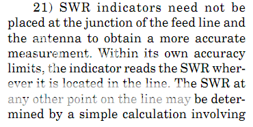
while vswr will be lower the further away you move from the antenna you only need know the vswr at the point along the coax you insert the meter, the coax loss/attenuation per unit length and the distance between the meter and the antenna to calculate the vswr at the antenna ;)
 
bob85,
Thank you. I'm sorry, I don't know how to make a question any simpler than that. It had/has no hidden meanings, the question is exactly as stated.
I think your answer is very informative. Unfortunately, that's not a compliment.
- 'Doc
 
Interesting reading.

So what exactly is this thread trying to accomplish, or what information is being given.

If read from a new to the hobby person (newbie) it could be confusing.
 
Mack thanks for the reply. I watched the video, only thing I seen was a big ground plane.
 
In context, yes, it was correct. But your answer isn't for the question asked. There is -one- answer for that question, and only one.
- 'Doc
 
lets see if doc is as hollowheaded as the j-pole bandcampers, argue shit disrupt threads without ever posting anything from respected sources,

from the bird white papers

http://www.bird-technologies.com/re...R-Measurements-Using_In-Line-Power-Meters.pdf

bird.png

birdvswr1.png

birdvswr2.png


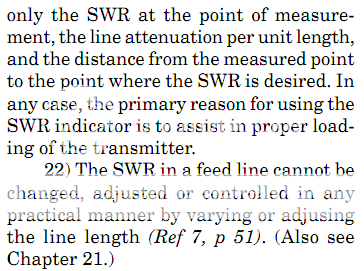
and from walt maxwell's Chapter 2, Countdown for a Journey from Mythology to Reality

waltmaxwell.png

walt.png

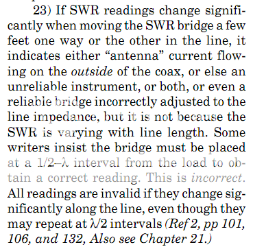
walt2.png


if doc / w5lz has anything factual to offer by way of proof that bird and walt are wrong this is his oportunity to step up to the plate,
if not then he should stop disrupting threads with his nonesense whenever technical topics are discussed.
 
"23) If SWR readings change significantly
when moving the SWR bridge a few
feet one way or the other in the line, it
indicates either “antenna” current flowing
on the outside of the coax, or else an
unreliable instrument, or both, or even a
reliable bridge incorrectly adjusted to the
line impedance, but it is not because the
SWR is varying with line length."


so CMC's may be the culprit behind folks having to use different coax lengths to make their meters happy ?

what is the bridge their talking about ?


bob , you know im gonna have to read that whole darn article now !!!! ;)
 
booty,
its up to you if you read them, im not saying walt or bird gets everything correct, theres more like that if you look around, depends on who you believe,
i alter my thinking when i find info that makes more sense to me than what i thought in the past, im always willing to learn and change my ideas(y)
 
"23)

what is the bridge their talking about ?

a swr bridge is a swr meter that uses an impedance bridge circuit to measure swr, when the swr is 1.0:1 the bridge is balanced and the needle has no movement, any other reading will cause imbalance in the bridge and cause current to flow giving a swr reading, similar idea to a psu bridge rectifier or ssb balanced modulator circuits, just used in a different context.

if you want to understand bridge circuits better than i can explain for you look up wheatstone bridge, one of the most popular and possibly the first bridge circuit used.
 
"23) If SWR readings change significantly
when moving the SWR bridge a few
feet one way or the other in the line, it
indicates either “antenna” current flowing
on the outside of the coax, or else an
unreliable instrument, or both, or even a
reliable bridge incorrectly adjusted to the
line impedance, but it is not because the
SWR is varying with line length."


so CMC's may be the culprit behind folks having to use different coax lengths to make their meters happy ?

what is the bridge their talking about ?


bob , you know im gonna have to read that whole darn article now !!!! ;)

3. The SWR in a feed line cannot be changed,
adjusted, or controlled in any practical manner
by varying or adjusting the line length.
TRUE

This is one of the most misunderstood concepts
in antennas, and we could spend pages
explaining the theory. The simple answer is
again that SWR on the line is determined by the
ratio of the load impedance to the characteristic
impedance of the line.
Line length (assuming
low feed line loss) CANNOT change the SWR.
We can discuss the mathematical proof over a
Coke. There is something of a trick to this
question. There’s a difference between the SWR
on the line and the effective INPUT impedance
seen at the input connector to the antenna
system. Changing the line length (thus electrical
line length) can change the input impedance
making it easier for a tuner to match the line to
the transmitter.
 
"just remember what theory means and take it with a grain of salt."

interesting comment , maybe worthy of a thread by itself . "theory" seems to mean different things to different people and i see on different forums folks labeling proven scientific fact as theory . i think sometimes the differences folks see isn't caused by the reason they think , so they assume theory is or must be wrong . big name long established CB antenna companies don't help matters skewing information to promote their products (eg. firestick) and neither do the smaller custom/"premium" CB antenna builders (eg. 55 , coily , etc.) .

im proof you dont have to know much about antennas to build one that works pretty well .
the key to selling them is to have the tools/laith and mechanical talent to make them look pretty .

.............a few nut huggers extolling its virtues and superior performance doesn't hurt either ;)
 

Attachments

  • Nuthugger.jpg
    Nuthugger.jpg
    24.2 KB · Views: 41
Last edited by a moderator:
Status
Not open for further replies.

dxChat
Help Users
  • No one is chatting at the moment.