• You can now help support WorldwideDX when you shop on Amazon at no additional cost to you! Simply follow this Shop on Amazon link first and a portion of any purchase is sent to WorldwideDX to help with site costs.

Tram D201 original VOX radio. Learned a new trick . Really!

nomadradio

Analog Retentive
Apr 3, 2005
7,001
11,188
698
Louisville, KY
www.nomadradio.com
You would think that after 44 years I would have learned all the tricks to fix design quirks in a radio like the original "VOX" Tram D201.

Not quite.

Even after all 20 electrolytic capacitors have been replaced there is an annoying 120-Hz "hum" in the receiver speaker, even with the volume control turned all the way down. Now, most users of this radio don't turn the volume control to zero, so I have largely ignored it all these years. With the volume turned up, and the channel noise it's not that noticeable.

But now I need to sell this radio, and that hum annoyed me. Seemed a little louder than normal for this model, to boot.

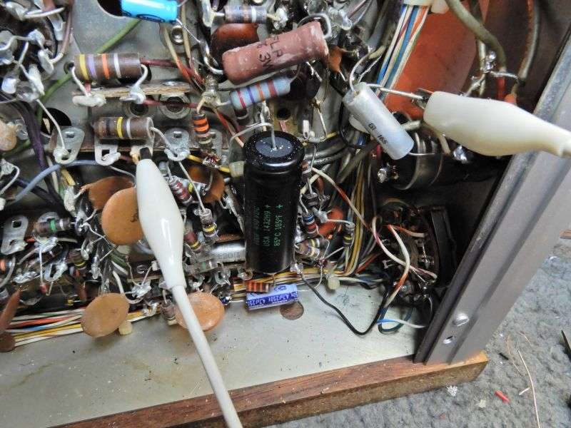
After a bit of head-scratching, I found that the chassis-ground connection on the volume/tone control was the culprit.

2qFzgB.jpg


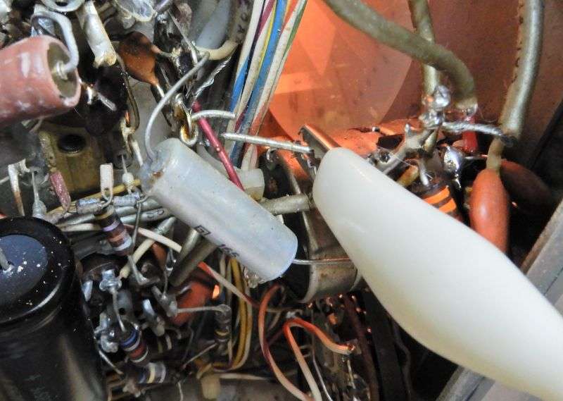
I cut the fat bare wire between the control and a chassis ground lug and ran a gator lead to a ground lug alongside the 12AX7 volume-control preamp/squelch tube V402.

BV7tl8.jpg


BINGO! There is still a bit of 60-Hz 'buzz' sound if you put your ear up to the speaker, but this was a big improvement. At a distance of a couple of feet, no more 120-Hz hum.

No need for a pic of the final version, a wire soldered to the volume-control ground at one end, and to the ground lug at the other.

Just goes to show that there's always a new trick to be learned, no matter how old a dog you are.

73
 
Last edited:

That's the deal. A better ground point for the volume/tone control. There was a small voltage difference between the ground lug the factory used for the volume control and the ground alongside the tube that the volume control feeds into.

The voltage drop doesn't need to be much. One millivolt of 120-Hz rectifier ripple will be audible in the receiver speaker.

Ground-circuit design is not an intuitive fall-off-of-a-log proposition.

If it was I would have figured this out decades ago.

73
 
Last edited:
Then it would explain why I oftentimes in a Cobra or even Uniden - I see a jumper wire from the Audio amp chips' own Ground foil trace to the power filter cap ground pad. The trace needs as much help as it can get I guess...

But it was the 120Hz (Rectifier hum) that clued you in on it?
 
  • Like
Reactions: tecnicoloco
Uh, yeah.

A full-wave rectifier like the Tram uses for the B+ supply produces two ripple peaks for each 60-Hz cycle. A 'hum' problem that's the fault of the B+ supply will have an audible pitch one octave above the familiar 60-Hz hum at 120 Hz. It's easier to tell one from the other with a little practice.

A 60-Hz hum in this radio is usually caused by the 6.3 Volt AC heater supply. The tube sockets each have a metal saddle that provides ground lugs. This radio simply grounds each tube's heater to the tube socket's mount ring. They were thoughtful enough to put a tooth washer between the socket and chassis under each of the two rivets that fasten each tube socket to the chassis. This reduces the resistance between the socket's ground ring and the chassis. But the voltage drop can be enough to "piggyback" that 60-Hz AC waveform into the signal circuits that share the same ground point.

I should post the one fix we worked out years ago for 60-Hz hum in the mike audio. We take the ground wire loose from pin 4 on the mike preamp tube's socket V601 and run a wire from that lug all the way to the rear of the chassis where the transformer's heater winding is grounded to the chassis. Fixes the transmit-side 60-Hz AC hum problem.

I tried this trick first on V402, the volume-control amp/squelch tube. Couldn't hear a difference. The biggest improvement was to the 120-Hz B+ ripple "hum" caused by the choice of ground point for the volume control. .

If I were really interested, I could put the heater pin's ground back where it was before on V402 and compare.

But what I'm really interested in is getting the bloody thing sold. One customer in Indy has dibs on it. We'll soon see if he puts his money where is mouth is.

If not, I'll be hawking a really clean D201 VOX radio with a digital frequency display and full-swing carrier control.

73
 
Uh, yeah.
... They were thoughtful enough to put a tooth washer between the socket and chassis under each of the two rivets that fasten each tube socket to the chassis. This reduces the resistance between the socket's ground ring and the chassis. But the voltage drop can be enough to "piggyback" that 60-Hz AC waveform into the signal circuits that share the same ground point.

I should post the one fix we worked out years ago for 60-Hz hum in the mike audio. We take the ground wire loose from pin 4 on the mike preamp tube's socket V601 and run a wire from that lug all the way to the rear of the chassis where the transformer's heater winding is grounded to the chassis. Fixes the transmit-side 60-Hz AC hum problem.

This is what I find so interesting - it goes against common practice from just about every major manufacturer these days, to run long lengths of wire to simply solve a hum issue when they "Claim" it's poor ground dress leads...and trace utilization.

I'd like to know more because something that seems - out of the ordinary - works.

As I eluded too earlier, not all traces lead back to good grounding practices...

But what I'm really interested in is getting the bloody thing sold. One customer in Indy has dibs on it. We'll soon see if he puts his money where is mouth is.

If not, I'll be hawking a really clean D201 VOX radio with a digital frequency display and full-swing carrier control.

73

Prolly' could never afford it - but maybe someday when I grow up ... :)

Thanks for your insight, don't always get a chance to hear what your brain thinks like when you're at work or thinking of work.

This helps me for I am working on several "quirky" problems right now - dealing more with PC than audio but they have their faults too. So you have given me a break to think out of a box for a moment or two, at least it was a nice distraction. I don't know if I could ever repay for your kindness you've shown to the rest of us, but, in all my fun over here I may be able to keep you from making a poor investment - just don't buy a Dell...:sleep:
 
  • Like
Reactions: tecnicoloco
Next thing I would do is to tune that thing to the carrier frequency and sniff the output of the SSB filter.

Or maybe the input side, where the balanced modulator feeds into it.

It looks as if the spectrum of the hum spikes is held within the bandwidth of the crystal filter.

That should point to a source upstream of the filter.

Maybe it's coming from the audio, or maybe the carrier oscillator?

Next thing I would try is to listen to the signal first in SSB, next in FM mode, if you have that option.

For that matter, just sniff the carrier-oscillator output for 120 Hz FM, maybe?

Just a straw or two to grasp.

At.

73
 
  • Like
Reactions: tecnicoloco
First time I became aware of the need for a common "zero voltage" ground point was looking inside commercial tube-type PA amplifiers in high school. I was used to consumer grade record players and such, where the nearest chassis-ground point was what you would always see used.

The PA amplifiers had to have a low level of hum and noise when turned 'way up. A typical tube-type home stereo would flunk this test. These high-end PA amplifiers had a separate wire that carried the ground side of the tubes' heater circuit. That wire gets the 60-Hz AC voltage drop from the heater current.

A completely separate set of wires returned the tubes' cathode circuits to ground, along with all the controls' ground wires. But these ground wires carry only DC return current or audio-signal current.

All of them leading back to this one chassis-ground point.

Sure wish I could remember who it was that explained the reason for all that extra wire.

Years later, I was given the task of rebuilding a tube-type audio mixing board at the radio station where I worked. Sure enough, separate ground circuits for AC and signal circuits. Same reason. You need to be able to turn a pot all the way up without the audience hearing any hum on their end.

Just where you would encounter this in a textbook?

Pretty sure I have one of those here devoted to this subject.

Probably at the bottom of a tall pile. Haven't seen that one in a while.

Mostly I bought it to figure out RF-shielding design 25 years ago. But it turns out that your ground circuit is important for that, too.

If I uncover it, I'll post the title and author. And yes, I did learn a thing or ten from that one.

73
 
That would be good thing...for I'd like to know myself - for even in RF amp installs - it takes a single point grounding setup that makes or breaks a system when it comes to the ...

TamingOfTheShrew.jpg
Taming of the Shrew...
(Pretty Ain't it?)
Although based more upon a Shakespearian play, the effect is real - and as about as effusive, if not elusive - in coming to grips with real life events not playing fair in our world - no matter how much we tend to lean upon Ground Plane approach to shielding and common mode current issues.

So to keep you @kopcicle - I see your graphic and wanted to point out your situation is very if not - eerily similar to the one Nomad just solved.
GraticuledChart.jpg

Again, I see a 120 Henry Hertz - waltzing across your display...
 
This is my favorite all time radio. Never again will you see a manufacturer use 60 watts worth of tube dissipation between the modulator and final to make 4 watts of AM. The amount of headroom in unsurpassed. The only thing I couldn't stand was the D201 also has the loudest switching transient between RX and TX of any radio. The pop out of the speaker when you key or unkey the mic is way too much noise in a quiet setting.

On the non VOX Tram this is an easy fix. You just need a D-104 microphone that has receive switching contacts in it. I bypassed the pre-amp in a silver eagle to turn it into a "G" stand and the receive contact is wired to the extra ground pin on the Trams mic plug. It's wired to only ground the speaker winding on the audio transformer in RX and turns on and off with the mic. The mic contacts prevent the pop by automatically switching the speaker last. The VOX version will need an extra relay to bypass the modification and retain the VOX feature.

The group of 220 ohm 2 watt cathode resistors in the modulator stage is another area for improvement. They like to drift down in value and over heat the 6L6GC. They are also "spongy" because they have no regulation and reduce the peak output of the modulator. One simple fix is to place a 31 volt zener diode across the base - collector junction of an NPN pass transistor. This forms a high current, shunt regulator between its collector - emitter junction. Use this as a regulated bias source in place of the resistor string.

One last tip is never put a skinny Chinese 6L6GC tube in the modulator stage. These tubes are not up to the job and tend to either arc or over heat. You can tell a junk 6L6GC by the diameter of the glass envelope. Its glass sidewall is straight from top to bottom and is smaller in diameter than the Bakelite socket base. The better ones have a larger glass that only fits into the Bakelite socket because it flares inwards at the base where it meets the socket.
 
I second the motion on the skinny-straight sided 6L6GC tubes.

The first ones we encountered were made in the USSR. Not "Russia". They were branded GE. These started showing up around 1980 when their Owensboro plant was beginning to wind down production. The GE sales division would sell out of the US-made types, and buy these in bulk when the factory wasn't scheduled to make more of them in time. It was more important to fill orders than it was to restrict their supply to the GE factory.

The D201 would cause this tube to break down into secondary emission when used as the audio tube. Would blow the fuse on the BA board if you were lucky, or release a lot of smoke if you weren't. Behaved a bit better as a final, but never would show more than 2/3 or half the RF power the good tubes would get you.

Never tried any made in China, but I appreciate the heads up. Wacky part is that the closest thing to the one GE made in Owensboro comes from the Svetlana plant in Petersburg Russia. And those have straight sides, but slightly larger around than the plastic base. They don't bear the Svetlana name. In the USA that name belongs to an outfit in Long Island who makes them in a different russky factory. The ones actually made by Svetlana will have the name "Winged C", or "SED" as in Svetlana Electron Devices.

Just goes to show that the name printed on the carton or the tube often has nothing to do with who MADE the tube. Only who sold it.

73
 
Uh, yeah.

A full-wave rectifier like the Tram uses for the B+ supply produces two ripple peaks for each 60-Hz cycle. A 'hum' problem that's the fault of the B+ supply will have an audible pitch one octave above the familiar 60-Hz hum at 120 Hz. It's easier to tell one from the other with a little practice.

A 60-Hz hum in this radio is usually caused by the 6.3 Volt AC heater supply. The tube sockets each have a metal saddle that provides ground lugs. This radio simply grounds each tube's heater to the tube socket's mount ring. They were thoughtful enough to put a tooth washer between the socket and chassis under each of the two rivets that fasten each tube socket to the chassis. This reduces the resistance between the socket's ground ring and the chassis. But the voltage drop can be enough to "piggyback" that 60-Hz AC waveform into the signal circuits that share the same ground point.

I should post the one fix we worked out years ago for 60-Hz hum in the mike audio. We take the ground wire loose from pin 4 on the mike preamp tube's socket V601 and run a wire from that lug all the way to the rear of the chassis where the transformer's heater winding is grounded to the chassis. Fixes the transmit-side 60-Hz AC hum problem.

I tried this trick first on V402, the volume-control amp/squelch tube. Couldn't hear a difference. The biggest improvement was to the 120-Hz B+ ripple "hum" caused by the choice of ground point for the volume control. .

If I were really interested, I could put the heater pin's ground back where it was before on V402 and compare.

But what I'm really interested in is getting the bloody thing sold. One customer in Indy has dibs on it. We'll soon see if he puts his money where is mouth is.

If not, I'll be hawking a really clean D201 VOX radio with a digital frequency display and full-swing carrier control.

73
Do you have a writeup on that full swing carrier control Nomad? I have not found much on variable power for the tram. Also should I change out all of the electrolytics or just the paper ones, I have access to a variac to power it on slowly. Mine is the d201 vox with the limiter but not the blanker
 

dxChat
Help Users
  • No one is chatting at the moment.
  • @ Wildcat27:
    Hello I have a old school 2950 receives great on all modes and transmits great on AM but no transmit on SSB. Does anyone have any idea?
  • @ ButtFuzz:
    Good evening from Sunny Salem! What’s shaking?