
The 6-pole relay in the Tram D201 works pretty hard. The contacts will go bad if you use it long enough. A "when, not if" proposition.
The coil is designed for 110 Volts DC, with a resistance of 9000 ohms or more. Sounds odd, but there's a reason. The first version of the D201 had a VOX feature that keyed the radio from your voice into the mike. Only way to switch the relay with tubes calls for a coil that's a match for the high voltage, low current that a tube can control. Only the very-first D201 version had the VOX feature, all later revisions did not. But the relay remained the same until it was discontinued. One advantage of how Tram did this is that the mike switch only switches about 7 Volts into a tube, and the tube controls the high voltage to the relay. This way there is no shock hazard on the mike, the way a Browning can cause with its direct hookup from relay to mike socket.
45 years later, that version of this relay has become rare, only manufactured on special order. And the sole source of this relay gets a high price for it. And rightly so. The minimum order size from the factory was 500 pieces, last time I inquired. You have to pay up front, and the delivery time was ten weeks. He deserves a good markup on whatever he paid for them.
Even so, the 12-Volt DC version of this same relay is still listed as a current product. At about half or less the price of the 110-Volt version. If you're only fixing a single radio, this won't seem like a lot. But if you restock ten of them at a time for a repair business, that's a pinch. A hard pinch.
We started substituting a 12-Volt DC version of this relay some time back. It hurts less when I buy them for stock, and the combined part's price and labor to convert are about the same as the marked-up price I would have to charge for the original type part. Besides, if the customer needs another one down the road, it should be easier for him to obtain.
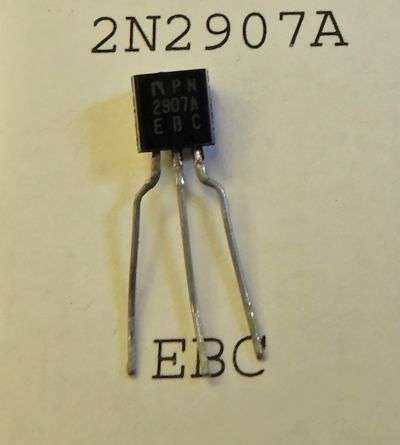
The changeover requires only one part that's added to the radio. A PNP transistor rated for at least 3/10 of an Amp. We use the 2N2907A/PN2907A. This is the part that Texas Star uses for the keying circuit in their amplifiers. We keep a lot of them on hand for this and other applications.
D201_12V_ry_trans
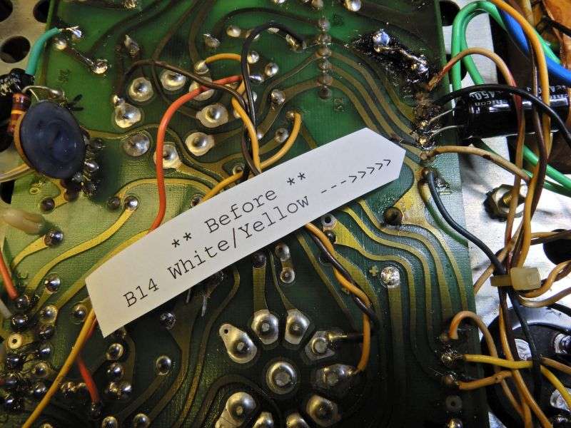
First change is to unsolder the white/yellow wire from pad B14 on the audio pc board.
BEFORE:
D201_12V_ry_whi_yell_b4
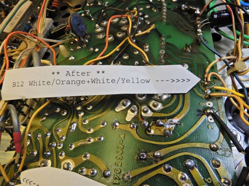
This wire gets moved to pad 12, soldered where the white/orange wire is already attached.
AFTER:
D201_12V_ry_whi_yell_after
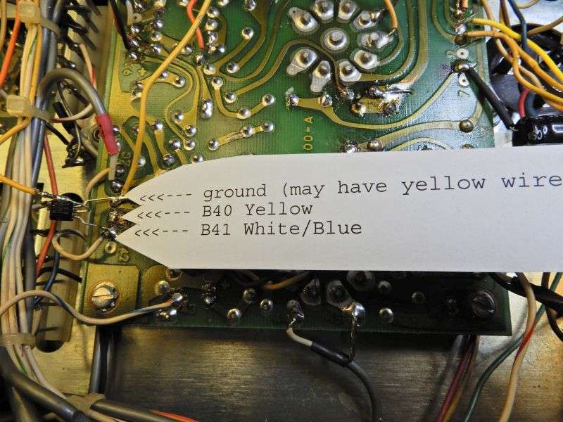
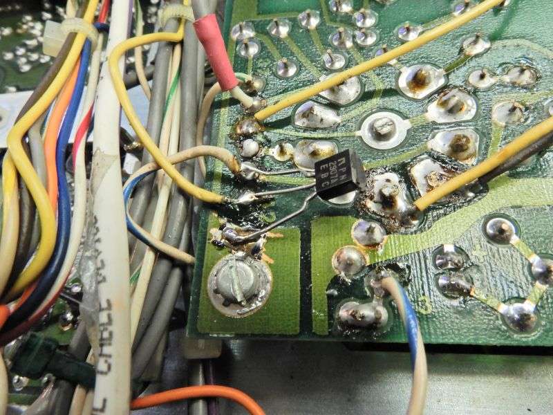
At the front-inboard corner of the audio board are these three pads. Unsolder the yellow wire from pad B40. The transistor gets its collector soldered to a ground trace, the emitter to pad 41, where a white/blue wire is already connected and the loose end of the yellow wire is lap-soldered to the base lead of the transistor.
D201_12V_ry_keying_trans
D201_12V_ry_keying_trans_2
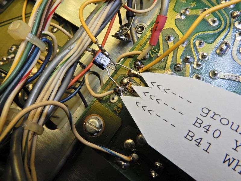
Yeah, this looks a bit shaky. Wouldn't be smart to do it this way in a mobile radio, but a base station probably won't shake it loose.
There's more than one way to skin a cat. This method is more secure, but you'll need to clip one end of R610, a 100k resistor connected to this foil trace to do it this way.
D201_12V_ry_trans_other_way
And that's all it takes. The white/yellow wire in the first step delivers the coil voltage to the "hot" side of the relay coil. The white/orange wire where it's moved supplies 14 Volts DC. The blue/white wire at B41 is the other "cold" side of the relay coil. This wire gets a connection to ground through the transistor when the yellow wire connects to ground back through the mike jack and mike.
One little detail worth noting has to do with the 14-Volt regulator transistor on the "BA" plug-in board. This will increase the load on that transistor, and the heat that it must dump. Any added surface area on the tiny heat sink will help. Doesn't have to be pretty, just needs to give the transistor's heat more surface area. This will prevent that transistor from running hotter than it already does.
Best of luck, and remember. If you break it you have the pieces.
PS: Potter and Brumfield part numbers:
5-Amp contact version is R10-E1-X6-V90
7.5-Amp rated is R10-E1-W6-V90
Magnecraft with 5-Amp contacts is W67RCSX-12.
Mouser, Newark, Arrow, Element 14 and others should list one or both of these.
73
The coil is designed for 110 Volts DC, with a resistance of 9000 ohms or more. Sounds odd, but there's a reason. The first version of the D201 had a VOX feature that keyed the radio from your voice into the mike. Only way to switch the relay with tubes calls for a coil that's a match for the high voltage, low current that a tube can control. Only the very-first D201 version had the VOX feature, all later revisions did not. But the relay remained the same until it was discontinued. One advantage of how Tram did this is that the mike switch only switches about 7 Volts into a tube, and the tube controls the high voltage to the relay. This way there is no shock hazard on the mike, the way a Browning can cause with its direct hookup from relay to mike socket.
45 years later, that version of this relay has become rare, only manufactured on special order. And the sole source of this relay gets a high price for it. And rightly so. The minimum order size from the factory was 500 pieces, last time I inquired. You have to pay up front, and the delivery time was ten weeks. He deserves a good markup on whatever he paid for them.
Even so, the 12-Volt DC version of this same relay is still listed as a current product. At about half or less the price of the 110-Volt version. If you're only fixing a single radio, this won't seem like a lot. But if you restock ten of them at a time for a repair business, that's a pinch. A hard pinch.
We started substituting a 12-Volt DC version of this relay some time back. It hurts less when I buy them for stock, and the combined part's price and labor to convert are about the same as the marked-up price I would have to charge for the original type part. Besides, if the customer needs another one down the road, it should be easier for him to obtain.
The changeover requires only one part that's added to the radio. A PNP transistor rated for at least 3/10 of an Amp. We use the 2N2907A/PN2907A. This is the part that Texas Star uses for the keying circuit in their amplifiers. We keep a lot of them on hand for this and other applications.
D201_12V_ry_trans
First change is to unsolder the white/yellow wire from pad B14 on the audio pc board.
BEFORE:
D201_12V_ry_whi_yell_b4
This wire gets moved to pad 12, soldered where the white/orange wire is already attached.
AFTER:
D201_12V_ry_whi_yell_after
At the front-inboard corner of the audio board are these three pads. Unsolder the yellow wire from pad B40. The transistor gets its collector soldered to a ground trace, the emitter to pad 41, where a white/blue wire is already connected and the loose end of the yellow wire is lap-soldered to the base lead of the transistor.
D201_12V_ry_keying_trans
D201_12V_ry_keying_trans_2
Yeah, this looks a bit shaky. Wouldn't be smart to do it this way in a mobile radio, but a base station probably won't shake it loose.
There's more than one way to skin a cat. This method is more secure, but you'll need to clip one end of R610, a 100k resistor connected to this foil trace to do it this way.
D201_12V_ry_trans_other_way
And that's all it takes. The white/yellow wire in the first step delivers the coil voltage to the "hot" side of the relay coil. The white/orange wire where it's moved supplies 14 Volts DC. The blue/white wire at B41 is the other "cold" side of the relay coil. This wire gets a connection to ground through the transistor when the yellow wire connects to ground back through the mike jack and mike.
One little detail worth noting has to do with the 14-Volt regulator transistor on the "BA" plug-in board. This will increase the load on that transistor, and the heat that it must dump. Any added surface area on the tiny heat sink will help. Doesn't have to be pretty, just needs to give the transistor's heat more surface area. This will prevent that transistor from running hotter than it already does.
Best of luck, and remember. If you break it you have the pieces.
PS: Potter and Brumfield part numbers:
5-Amp contact version is R10-E1-X6-V90
7.5-Amp rated is R10-E1-W6-V90
Magnecraft with 5-Amp contacts is W67RCSX-12.
Mouser, Newark, Arrow, Element 14 and others should list one or both of these.
73
Last edited:


