
Like the title says, ditch that tired old digital clock for a 6-digit frequency display.
Not quite as tricky as it may sound. Does involve some detail, just the same.
One drawback to the SanJian PLJ6-LED frequency display. It has one and only one offset frequency you can program into it. The radio needs three of them, one for each mode.
Oops. The owner of this radio only cares about AM, so that's simple. Just have to add or subract 2.5 kHz when using a sideband mode.
Thought sure I had captured a "beauty shot" of the finished product as seen from the front.
Oops. Once the covers were back on it, making it go home distracted me from taking the "after" shots. Darn!
There are some potential conflicts between this display and this radio. First has to do with the two separate ground circuits, one for the chassis, and one connected to the DC power cord's black wire. The "DC" ground, or "pcb" ground.
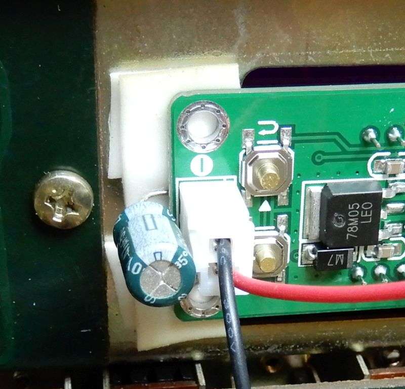
Keeping them separate means mounting the display with an insulator of some sort. The mount hole at each of the display board's four corners is a DC-circuit ground, and should not touch chassis metal. Copped out and used a high-strength double-sided adhesive foam called "VHB". The stuff from the drug store may or may not adhere as well. Just take a moment to wipe some rubbing alcohol or other solvent across the sides of the clock window before you attach the stuff.
But I'm getting ahead of myself. First you'll need to remove the clock. Fortunately it is a "beep" alarm clock only. It can't power up the radio when the alarm goes off. Other base stations that have that feature will require you to jump around the clock's alarm on/off switch. You can safely remove the small pc board under the chassis deck that has the tiny round alarm speaker on it.
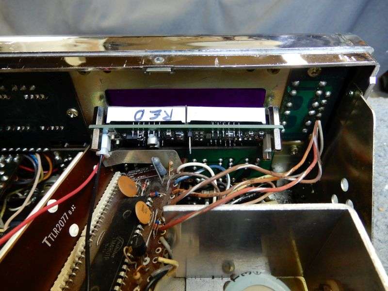
This clock is no big deal. Don't even have to remove the plastic front bezel, it comes out from the inside.
The 6-digit display WILL fit, but just barely.
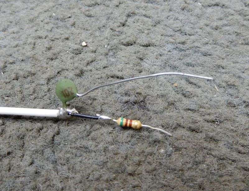
Remove the threaded spacers, we won't be using them. This pic shows a green filter capacitor you can safely ignore. Found we don't need it in this radio, so long as we power it through a resistor. I used two layers of the double-stick foam, to make sure no pokey bits cut through the foam and touch the chassis metal.
The gap in the second foam layer was for the capacitor. Don't need to do that, either. Two layers of foam the same size would work fine. Didn't bother to snap a new pic when we removed the capacitor.
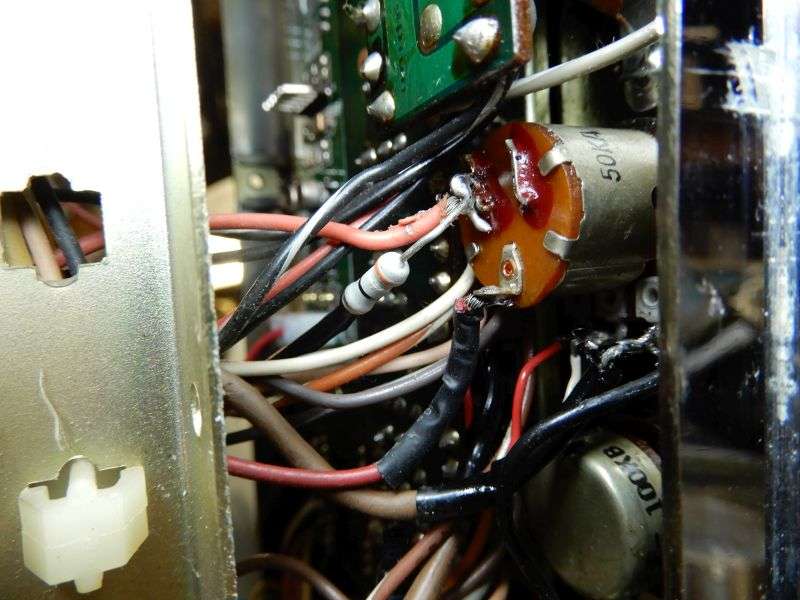
The power hookup needs an extension wire on the black negative lead, long enough to reach the pcb ground foil next to the big filter cap next to the audio chip.
The red wire gets a 39-ohm 1-Watt resistor in line with it. Would have used 47 ohm, but ran out that day.
The end of the resistor is soldered to the power switch. The side with the orange wire is the correct one. The red wire is the "always hot" DC power coming in to the power switch.
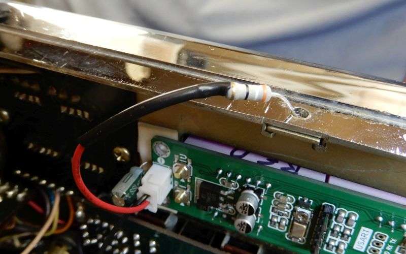
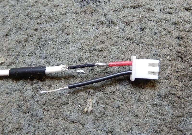
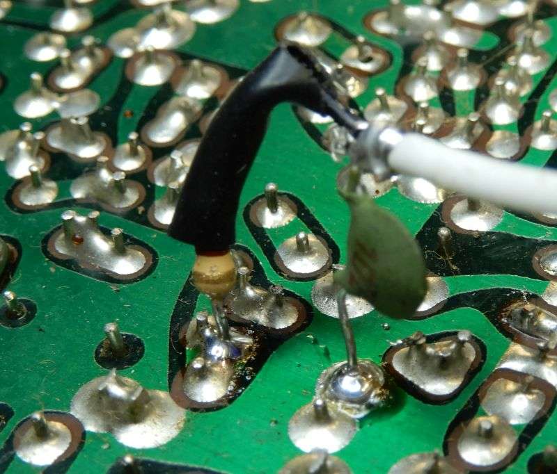
The signal-input gets special attention. First, we need a shielded lead and the display is supplied with a second JST plug with the same red and black wires as the power lead.
I prefer teflon coax. The tiny stuff is plenty flexible, and won't be melted by soldering directly to the shield braid.
**** WURD OF WARNING ****
Be sure to check the polarity of the signal cable. The input socket has a "~" for the hot side and a ground symbol on the other pin. Never mind the color of the wires, just be sure to keep hot on hot and ground on ground. The hot side is red on this plug, but check this first.
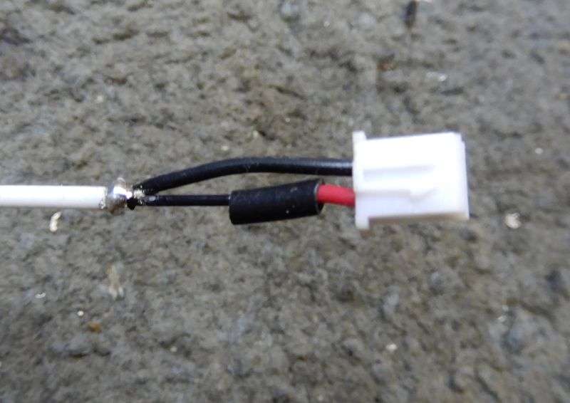
This is the biggest advantage of using teflon coax. The shield is trimmed short, leaving just enough to wrap the stripped end of the black wire around it. Solder it after sliding down the sleeve that protects the red wire's lap splice.
Kinda protects it.
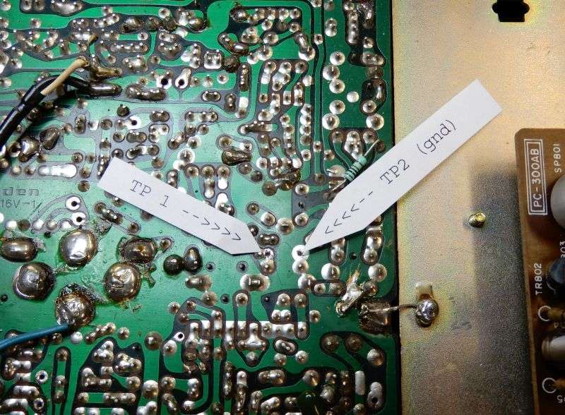
The tapoff end of the input coax gets two components attached to it. A .001 (102) ceramic disc has one side on the coax shield, and the other side will go to ground at TP2 on the solder side of the pc board. This provides a ground path for the PLL output signal we will be counting, but prevents a DC-ground loop that can introduce scanning noises into the receiver. The 510-ohm resistor can probably be any value from 220 to 1000 ohms, but this is what we used when I ran out of 470 ohm. Worked fine.
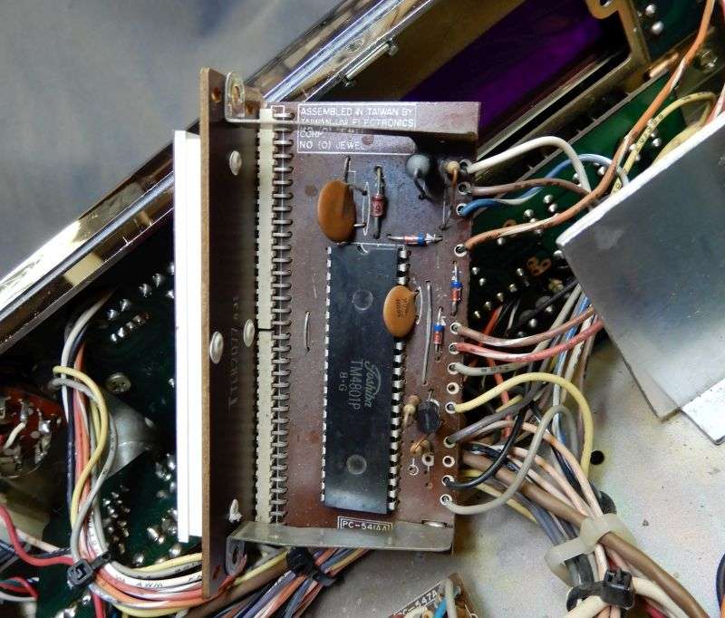
Here are test points one and two on this pc board. Should have made a note of the pcb number.
It's a base station, so flimsy stuff like this hookup should not create a liability.
Kinda wish I had gotten that beauty shot of the radio's front panel after the install. Had to turn down the display's brightness setting at "2" to keep it from overwhelming the dim red 1978 channel digits.
Just beware of Uniden SSB radios with the 858 chip. It shifts frequency by 2.5 kHz in AM mode when you key the mike.
Odd, but at least this radio and all the other MB8719 SSB CBs will read correctly on AM. Or on one of the two sideband modes, only if you preset the display's offset for that mode. Only.
This is by no means the only way to go about it, but trial and error led us to it. Hasn't failed for us yet.
Your mileage may vary.
73
Not quite as tricky as it may sound. Does involve some detail, just the same.
One drawback to the SanJian PLJ6-LED frequency display. It has one and only one offset frequency you can program into it. The radio needs three of them, one for each mode.
Oops. The owner of this radio only cares about AM, so that's simple. Just have to add or subract 2.5 kHz when using a sideband mode.
Thought sure I had captured a "beauty shot" of the finished product as seen from the front.
Oops. Once the covers were back on it, making it go home distracted me from taking the "after" shots. Darn!
There are some potential conflicts between this display and this radio. First has to do with the two separate ground circuits, one for the chassis, and one connected to the DC power cord's black wire. The "DC" ground, or "pcb" ground.
Keeping them separate means mounting the display with an insulator of some sort. The mount hole at each of the display board's four corners is a DC-circuit ground, and should not touch chassis metal. Copped out and used a high-strength double-sided adhesive foam called "VHB". The stuff from the drug store may or may not adhere as well. Just take a moment to wipe some rubbing alcohol or other solvent across the sides of the clock window before you attach the stuff.
But I'm getting ahead of myself. First you'll need to remove the clock. Fortunately it is a "beep" alarm clock only. It can't power up the radio when the alarm goes off. Other base stations that have that feature will require you to jump around the clock's alarm on/off switch. You can safely remove the small pc board under the chassis deck that has the tiny round alarm speaker on it.
This clock is no big deal. Don't even have to remove the plastic front bezel, it comes out from the inside.
The 6-digit display WILL fit, but just barely.
Remove the threaded spacers, we won't be using them. This pic shows a green filter capacitor you can safely ignore. Found we don't need it in this radio, so long as we power it through a resistor. I used two layers of the double-stick foam, to make sure no pokey bits cut through the foam and touch the chassis metal.
The gap in the second foam layer was for the capacitor. Don't need to do that, either. Two layers of foam the same size would work fine. Didn't bother to snap a new pic when we removed the capacitor.
The power hookup needs an extension wire on the black negative lead, long enough to reach the pcb ground foil next to the big filter cap next to the audio chip.
The red wire gets a 39-ohm 1-Watt resistor in line with it. Would have used 47 ohm, but ran out that day.
The end of the resistor is soldered to the power switch. The side with the orange wire is the correct one. The red wire is the "always hot" DC power coming in to the power switch.
The signal-input gets special attention. First, we need a shielded lead and the display is supplied with a second JST plug with the same red and black wires as the power lead.
I prefer teflon coax. The tiny stuff is plenty flexible, and won't be melted by soldering directly to the shield braid.
**** WURD OF WARNING ****
Be sure to check the polarity of the signal cable. The input socket has a "~" for the hot side and a ground symbol on the other pin. Never mind the color of the wires, just be sure to keep hot on hot and ground on ground. The hot side is red on this plug, but check this first.
This is the biggest advantage of using teflon coax. The shield is trimmed short, leaving just enough to wrap the stripped end of the black wire around it. Solder it after sliding down the sleeve that protects the red wire's lap splice.
Kinda protects it.
The tapoff end of the input coax gets two components attached to it. A .001 (102) ceramic disc has one side on the coax shield, and the other side will go to ground at TP2 on the solder side of the pc board. This provides a ground path for the PLL output signal we will be counting, but prevents a DC-ground loop that can introduce scanning noises into the receiver. The 510-ohm resistor can probably be any value from 220 to 1000 ohms, but this is what we used when I ran out of 470 ohm. Worked fine.
Here are test points one and two on this pc board. Should have made a note of the pcb number.
It's a base station, so flimsy stuff like this hookup should not create a liability.
Kinda wish I had gotten that beauty shot of the radio's front panel after the install. Had to turn down the display's brightness setting at "2" to keep it from overwhelming the dim red 1978 channel digits.
Just beware of Uniden SSB radios with the 858 chip. It shifts frequency by 2.5 kHz in AM mode when you key the mike.
Odd, but at least this radio and all the other MB8719 SSB CBs will read correctly on AM. Or on one of the two sideband modes, only if you preset the display's offset for that mode. Only.
This is by no means the only way to go about it, but trial and error led us to it. Hasn't failed for us yet.
Your mileage may vary.
73
Last edited:
