• You can now help support WorldwideDX when you shop on Amazon at no additional cost to you! Simply follow this Shop on Amazon link first and a portion of any purchase is sent to WorldwideDX to help with site costs.

Tricky Schematics

paws264

Active Member
Apr 6, 2005
646
12
28
While attempting to help a guy out with his amp, I went to that Tricky CB site and looked up the electrical road map for the amp in question.

SANY8110.jpg
Can someone help me with info on this part pointed out in the photo ?? Put too much into the amp and burned this part.

I found this schematic:

cb.jpg


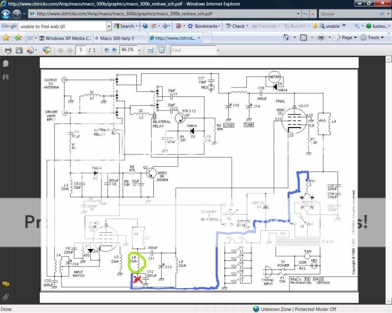
It is mistakenly drawn and cannot be used, it should be corrected. there are two mistakes on the drawing, one where the high voltage is ties to ground and another mistake where the tank coil for the driver section has been completely deleted. Compare this drawing to the re-drawn .PDF file.

tricky1.jpg


I wonder how many more drawings there are like this and, will they be corrected any time soon?

.
 
Last edited:

It's a coil. And the rest of the amp looks a little old and nasty too. Any roaches come crawling out when you took the cover off?
2mpe5id.gif
 
Last edited:
Are we talking about L6? It's a plate choke and not a very good one at that from the looks of it. Plate chokes are not critical as to value as long as they have enough inductance at the lowest freq of operation. Get a piece of ferrite bar from an old AM radio,cover it with some insulating tape, and wind it completely from end to end with small wire and the job is done.Tell him next time to take it easy on the input drive.
 
Are we talking about L6? It's a plate choke and not a very good one at that from the looks of it. Plate chokes are not critical as to value as long as they have enough inductance at the lowest freq of operation. Get a piece of ferrite bar from an old AM radio,cover it with some insulating tape, and wind it completely from end to end with small wire and the job is done.Tell him next time to take it easy on the input drive.


All very good 'cept for one thing, in my experience, it has been good engineering practice to use Teflon or some other highly resistive material (Bakelite) as the form to wind your High Voltage Plate Choke on.

If, we look at the diagram, you will see that there are no dotted lines associated with the B+ Choke indicating that there is not a magnetic core involved.

If, you are constructing / repairing a Bifilar Cathode Choke for directly heated Triode tubes then, by all means, a ferrous core is required but not for the plate circuit.

.
 
Does anyone know what the choke on the bottom left hand side is in this pic.?

22uH. It is a protection device for if C11, the .005 uF cap would happen to short there would be high voltage going to the antenna. With the choke being there it would short the high voltage power supply to ground and hopefully R11, the 2 ohm 10 W wirewound resistor would open up, killing the high voltage.
 

dxChat
Help Users
  • No one is chatting at the moment.