• You can now help support WorldwideDX when you shop on Amazon at no additional cost to you! Simply follow this Shop on Amazon link first and a portion of any purchase is sent to WorldwideDX to help with site costs.

Tube biasing help

Champo

Active Member
May 3, 2021
227
33
38
42
Oregon
What causes the grid on a final output tube to go negative in respect to the cathode upon transmit and what would prevent this from happening?

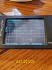
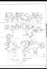
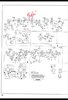
The reason for my question is that I have a Regency Range Gain that will only key .75 watts and swing to 1.5 watts rather than the 1.6 watts swinging to 10 watts. It has been recapped, resistors checked, aligned and new tubes tried without success. Everything checks out except for the final tube voltage. As you can see on the included pic, the grid (Pin #2, V12 - 12BH7) should be at -16VDC during transmit and in my case the voltage remains positive and is about the same as the cathode; approximately 14VDC. I suspect this is my problem but I have had a very difficult time finding a good explanation on what in the circuit drives the voltage negative and why it isn't occurring in my case. Thank you for your help!
 

Attachments

  • Screenshot_20211024-023135_Drive.jpg
    Screenshot_20211024-023135_Drive.jpg
    399.9 KB · Views: 10
  • Screenshot_20211024-023204_Drive.jpg
    Screenshot_20211024-023204_Drive.jpg
    440.2 KB · Views: 10
  • Screenshot_20211024-023224_Drive.jpg
    Screenshot_20211024-023224_Drive.jpg
    468.6 KB · Views: 10
  • CB-13_Regency_RangeGain-II.pdf
    1.9 MB · Views: 9

Champo,
I still think tube V8 (Phase Inverter) is responsible.

73
David

Dmans thank you for your reply. The voltage values at the tube pins appear to be correct and a new tube did not change anything. Is there something else that I should look at or try regarding V8 (6AN8)? I also have that nanovna but I haven't found any helpful videos regarding troubleshooting the radio with it. Is there an application for it in this scenario? It does work great on my antenna though lol! :)

Jacob
Dmans,

Nomadradio mentioned K-Trans IF transformers being a problem. There are 4 in the radio but they appear to be in the receive strip. Do you think this is a factor? I never got a response from Nomadradio.

Thanks!

Jacob
 
Champo,
I believe I would check all the areas highlighted in yellow below. Paying particular attention to the relay contacts.

regency.gif

Search youtube for this guy.
imsai guy nanovna

It seems he has some interesting info on using the Nano VNA and actually shows tuning bandpass filters.


(I think it is this one ^^^. May help with your K-Trans IF Transformers.)

73
David
 
Dmans,

Thank you for the information. I'll give the VNA a shot. That video is very helpful.

Here are the current voltage and resistance values for the modulation trans and V9, V10 - 6AQ5 Output modulators. Values in parentheses are what I have and the value preceding it is what the Sam's calls for. Other than the difference between the resistance on the primary side of the trans everything appears to be correct.

Modulation Trans Resistance Primary
Brown-Red wires : 230 ohms (208 ohms)
Red-Blue wires : 230 ohms (229 ohms)

Modulation Trans Resistance Secondary
Green-Black wires : .7 ohms (.4 ohms)
Red/white-Blue/white wires : 540 ohms (527 ohms)

Modulation Trans Voltage Secondary
Receive
Red/White wire : 210vdc
Blue/White wire : 210vdc
Transmit
Red/White wire : 0vdc
Blue/White wire : 10.4vdc

V9 Output Modulator (6AQ5)
Pin 2 : 18v (17v)
Pin 5 : 300v (306v)
Pin 6 : 260v (256v)
Pin 7 : 0v (0v)

V10 Output Modulator (6AQ5)
Pin 1 : 0v (0v)
Pin 2 : 18v (16v)
Pin 5 : 300v (304v)
Pin 6 : 260v (257v)

These values are from about 10 minutes ago. Let me know your thoughts. Thank you for the help.

Jacob
 
Just to add. @guitar_199 requested that I compare values to a working Sonar FS-23 that I have. It follows the same pattern as the Regency where the grid goes negative during transmit. Here are the results:

"Interesting note on the Sonar. Pin 2 of V13 (final amp 6BQ5) on the final tube is -.17vdc and when keyed it drops to -.87vdc but not to the -8.6vdc that the Sam's calls out. I wonder if that is a simple decimal point error in the Sam's or a coincidence? It starts off at 0 but slowly ticks down to -.17vdc. After unkeying it will start out at 0 and slowly tick down (-.01, -.02, -.03 etc) until it bottoms out at -.17vdc.

Pin 1 of V12 (buffer amp 6AU6) follows a similar pattern. It starts off at 0 but slowly ticks down to -.45vdc and increases to -.40vdc but doesn't drop to the -3.8vdc the Sam's calls out. Again really close values (-3.8, -.40) if you move the decimal point. If you key up before it maxes out, say at -.17vdc it'll drop to the -.40vdc.

Nonetheless, the values are still negative whereas with the Regency they never go negative even to a minute degree."

Jacob
 
Modulation Trans Voltage Secondary
Receive
Red/White wire : 210vdc
Blue/White wire : 210vdc
Transmit
Red/White wire : 0vdc
Blue/White wire : 10.4vdc

Champo,
Because your Blue-White wire is not going to -18V in transmit, I would double check the relay contact(s) and C66 and R51* (tied to Pin 9 of tube V8). Are you seeing 18V at pin 9 of tube V8 during transmit? (Or 20V per the Range Gain II schematic?)

Do you have voltage measurements from the modulation transformer primary during transmit and receive?

*It is interesting that the Range Gain schematic and Range Gain II schematic have these two components reversed??

73
David
I haven't actually checked the value at V9/V10 during transmit. I can get that value. I've only done it during receive.

As for the Sam's. It's so wonky for this radio it's amazing. CB-13 is more accurate for the most part however there are things on the receive side that are wrong in CB-13 but right in CB-5. They're minor but I've never come across a Sam's document that had been this butchered!
 
Dmans,

Here are the values. I've also included 2 pics.

V8 Pin 9
Receive : 16.2vdc
Transmit : 17.7vdc

After R55
Receive : 14.7vdc
Transmit : 16vdc

Blue/white Transformer
Receive: 208vdc
Transmit : 10.7vdc

Primary Modulation Trans wires
Brown (V9)
Receive : 304vdc, Transmit : 303vdc
Blue (V10)
Receive : 303vdc, Transmit : 302vdc
Red
Receive : 309vdc, Transmit : 308vdc

Jacob
 

Attachments

  • Screenshot_20211024-190527_Gallery.jpg
    Screenshot_20211024-190527_Gallery.jpg
    529.3 KB · Views: 7
  • 20211024_185559.jpg
    20211024_185559.jpg
    1.8 MB · Views: 6
Champo,
Because this unit is a Double Sideband radio (suppressed carrier) I would think all "Transmit" measurements should be made with audio injected at the mike socket for proper results.

-Tube V7b acts on tube V8a thru R3 (modulation level control) and K1 relay contacts 6 & 10.
-K1 relay contacts 9 & 4 ground the secondary of T2 during transmit
-Tube V8b acts on V9 and V10 during transmit
-V9 is fed from the anode of V8
-V10 is fed from the cathode of V8

These would be the next items I would look closely at.

73
David
 
Seems to me that Aerovox cap is leaking (droplets on case) Also looks like paper case breaking down near "Black" solder joints.
That Bias voltage is switched via relay somewhere, it will not just swing that way under transmit.
You must check to see where it is derived from and follow the path when switched to the PA section.
That radio at best should DK about 3 watts, mod forward to maybe 8 watts PEP(5 watts average) that's just how they were built in those days by rules. To get anymore than that requires "strapping" the screen voltage or increasing the B+, then even still maybe 10-12 watts PEP. Doing this however will sacrifice tube life. IMHO
I had and Imperial w/DSB mod...about 9-10 watts PEP...Am about 2.5 watts mod forward to about 5 watts.
 
Champo,
Because this unit is a Double Sideband radio (suppressed carrier) I would think all "Transmit" measurements should be made with audio injected at the mike socket for proper results.

-Tube V7b acts on tube V8a thru R3 (modulation level control) and K1 relay contacts 6 & 10.
-K1 relay contacts 9 & 4 ground the secondary of T2 during transmit
-Tube V8b acts on V9 and V10 during transmit
-V9 is fed from the anode of V8
-V10 is fed from the cathode of V8

These would be the next items I would look closely at.

73
David

Appreciate it Dmans! I'll take a look there next.

Jacob
 
Seems to me that Aerovox cap is leaking (droplets on case) Also looks like paper case breaking down near "Black" solder joints.
That Bias voltage is switched via relay somewhere, it will not just swing that way under transmit.
You must check to see where it is derived from and follow the path when switched to the PA section.
That radio at best should DK about 3 watts, mod forward to maybe 8 watts PEP(5 watts average) that's just how they were built in those days by rules. To get anymore than that requires "strapping" the screen voltage or increasing the B+, then even still maybe 10-12 watts PEP. Doing this however will sacrifice tube life. IMHO
I had and Imperial w/DSB mod...about 9-10 watts PEP...Am about 2.5 watts mod forward to about 5 watts.

BJ,

I would gladly take 3 watts swinging 8. The Owner's manual says 1.6 swinging 10 but even 1.6 swinging 8 would good. I have a Sonar FS-23 that keys 2.5 and swings 5 and it's killing the Regency right now. There's definitely something up with the Regency. Right now it keys .75 and swings 1.5 with a whistle. This is with R3 (modulation adjustment) all the way up which is leading to feedback in the speaker. In reality it isn't even swinging the 1.5. I'll take a look at the cap and those other locations. I appreciate the input.

Jacob
 
Champo,
I believe I would check all the areas highlighted in yellow below. Paying particular attention to the relay contacts.

View attachment 47969

Search youtube for this guy.
imsai guy nanovna

It seems he has some interesting info on using the Nano VNA and actually shows tuning bandpass filters.


(I think it is this one ^^^. May help with your K-Trans IF Transformers.)

73
David

Dmans,

Thanks again for the VNA lead. I ran through the different adjustments with the VNA and I think I have them dialed in. Let me know if you think they look correct. I do have a question about the crystal adjustments for the 4 crystals starting with 8xxx. I could not get them centered. The best I could do was the right side of the dip. I can move the dip to the left away from the crystals get them to level out but that's it. They do have the proper spikes at their corresponding frequencies though. I need to double check the 1xxxx crystals to see if they're in a similar boat but I ran out of time.
Pic 1 - A18 (7.5 crystal)
Pic 2 - A15 (8xxx crystals)
Pic 3/4 - A16/17
Pic 5 - A19/20
Pic 6 - A21/22

Thanks

Jacob
 

Attachments

  • 20211026_014901.jpg
    20211026_014901.jpg
    1.5 MB · Views: 7
  • 20211026_014632.jpg
    20211026_014632.jpg
    1.5 MB · Views: 6
  • 20211026_013123.jpg
    20211026_013123.jpg
    1.4 MB · Views: 4
  • 20211026_012401.jpg
    20211026_012401.jpg
    1.3 MB · Views: 4
  • 20211026_010439.jpg
    20211026_010439.jpg
    3.2 MB · Views: 4
  • 20211026_005212.jpg
    20211026_005212.jpg
    3.3 MB · Views: 4
  • Like
Reactions: Dmans

dxChat
Help Users
  • No one is chatting at the moment.
  • @ Wildcat27:
    Hello I have a old school 2950 receives great on all modes and transmits great on AM but no transmit on SSB. Does anyone have any idea?
  • @ ButtFuzz:
    Good evening from Sunny Salem! What’s shaking?
  • dxBot:
    63Sprint has left the room.