• You can now help support WorldwideDX when you shop on Amazon at no additional cost to you! Simply follow this Shop on Amazon link first and a portion of any purchase is sent to WorldwideDX to help with site costs.

Twin X-Mount Dipole Idea

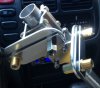
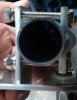
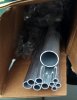
Just got some of my antenna tubing from DX Engineering and the second MFJ-347. Fast fast fast!
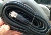
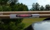
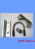
This is for the reflector and boom. I'd make the driven element out of the same type material if I knew where to get some dipole insulated posts.
 

Attachments

  • image.jpg
    image.jpg
    420.2 KB · Views: 5
Last edited:
Two MFJ-347's on a DX Engineering 1.250" .58 thick tube. I may order a 1.50" 1.20 thick 6' tube for the boom. That will allow the 1.250 OD tube to fit in the 1.50" tube. Unless I'm wrong,I need a boom length of 7'. Driven element to reflector spacing is around 6.35' for wide bandwidth.


P.S. I wonder if a thin plastic sleeve or electrical tape to electrically isolate the MFJ-347's from the boom will work right ?
 

Attachments

  • image.jpg
    image.jpg
    230.8 KB · Views: 3
Last edited:
Mounting Yagi Antenna Mounts | ASTRON WIRELESS
http://forums.qrz.com/archive/index.php/t-204266.html
However, if all the options are open to you, I'd recommend using insulated elements mounted on top of the boom. This kind of antenna structure is simpler to analyse using modeling software. (You dont have to include the mounting bracket into the model). For six meters where the elements are relatively short the element mounting brackets are pretty easy to make. I like to use polyethylene kitchen cutting board that you saw into smaller blocks. You can get these for less than $10 at most department stores.
"For half inch diameter elements near the boom mounting plate, 4 or 5 inch long by 2.5 to 3 inch wide cutting board blocks will suffice for the parasitic elements. Drill some holes through on either side of the element and use uv stabilized zip ties to hold the element to the mounting block. Drill some holes for u-bolt sized for your boom diameter. You can use one or two per mounting block depending on how severe your weather environment is. For six meters you can get away with one if the antenna is not mounted on a high tower in a windy location.

The mounting bracket for the driven element may depend on the details of the feed structure. If it is a match that allows a continuous driven element (Gamma, Tee etc) then use the same approach as for the parasitic elements.

If the design uses a split driven element (Direct feed, Hairpin match etc) then you may need to use a little stronger mount bracket. This is because each side of the driven element will act as a lever on the mounting bracket. You can double thickness the cutting board, or use some other means to strengthen the driven element mounting bracket. You will need to use beefier method to attach the element halves to the bracket as well. This might just be more zip ties or you can use nuts and bolts."
http://www.moxonantennaproject.com/


http://www.cncplastics.com/
 
Last edited:
Okay. The manufacturer just em'd me back and said that the Procomm cophase harness has a VF factor if 78%
At 27.205 MHz the cophase harness would have to be 7.054 feet (7 feet 21⁄32 inch) long. I wonder if the overall feed line lenght would have to be adjusted to compensate?
 
Last edited:
I'm wanting to make a element to boom hub. Time to get creative. I'm expecting my three 102" SS whips today. I wonder if I may just temporarily mount them horizontal turnstile configuration until I figure out and make the boom/reflector part of it and turn the whole antenna vertical.
File:Circular.Polarization.Circularly.Polarized.Light Right.Handed.Animation.305x190.255Colors.gif - Wikimedia Commons
I'm debating whether to set the cophase harness and 9' jumper to 1/4 electrical wavelength since they are all 9' long each and adjust the overall feed line length or cut adjust them. I think I'll adjust them. Already bought the amphenol PL-259 connectors. Just got my whips. Comments please.
P.S. I'm still waiting on the book I bought that has plans on how to make a CP antenna
http://www.cbcintl.com/CP_Beam.htm
 

Attachments

  • image.jpg
    image.jpg
    328 KB · Views: 3
Last edited:

dxChat
Help Users
  • No one is chatting at the moment.