
Fixing the clarifier to work properly on sideband involves two steps. Unhooking the transmit-only source of tuning voltage, usually from a trimmer pot.
And unhooking the receive-only voltage supply that powers the front panel clarifier/Delta Tune/VoiceLock control. Naturally, this includes connecting it to an continuous source of regulated DC voltage that's active all the time.
Okay, so that's three steps.
The Uniden Grant XL radio from the early-mid 1990s is nearly identical inside to the Philippines-made Cobra 148GTL from the late 80s. Wire colors might be different.
Taking loose the transmit-side voltage source requires removing at least one of two diodes D52 and D75. They're in series, so removing one does the same job as removing both. This is a "temperature compensating" diode, and has twice the usual 2/3 of a Volt forward drop when turned on. Removing both will permit stacking them in series, to use in place of a 'minimum carrier set' trimpot when installing variable carrier power. But that's another story for another day.
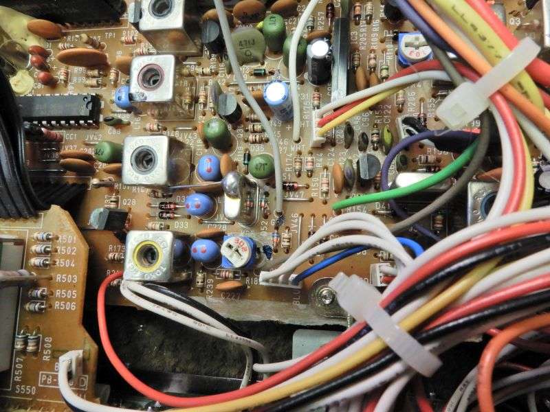
Here's the wide view of D52/D75. They're between the 11.325 crystal and VR5, the transmit-frequency trimmer pot.
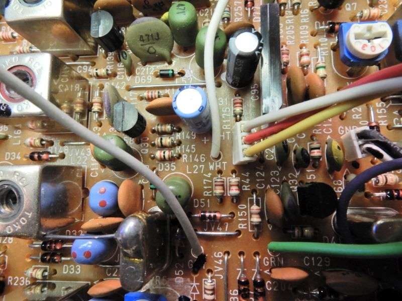
A closer view, with one diode removed.
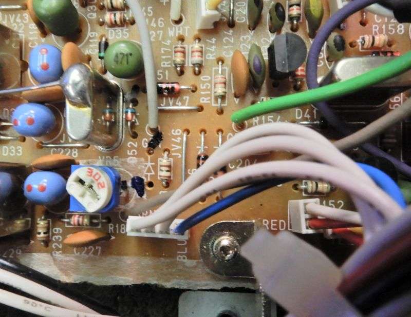
Next step is to find this wire. It's white in this radio, labeled "wht" on the board's screen print. This wire supplies power to the front-panel clarifier. I did say "find". Don't mess with this end of the wire.
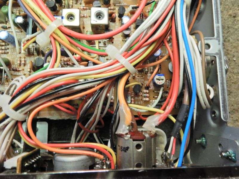
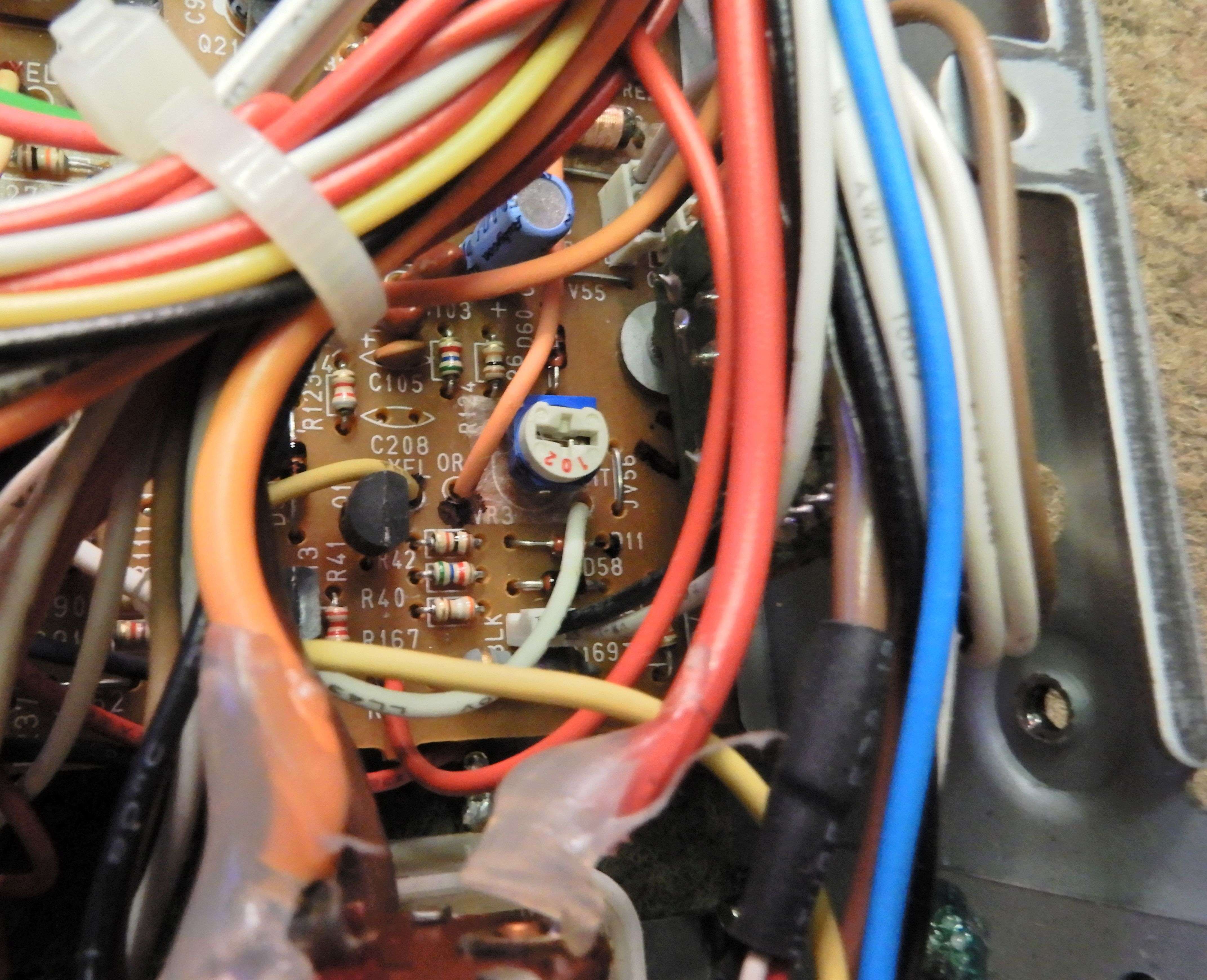
We need to follow this wire to the other end, at the front-corner of the main circuit board. Here's the wide view of the front corner of the circuit board, just behind the front-panel meter. The white wire we want attaches to the pc board just to the front of VR3. Unsolder this wire, pull this end out of the circuit board.
A closer-up view, with the white wire we want to pull out nearer the center of the image.
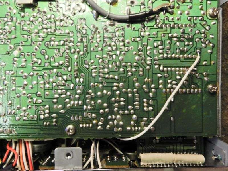
The free end of this wire will get passed through to the solder side of the pc board. Solder it to the pad under pin 9 of the MB8719 PLL chip. This will be the outermost, rearmost corner of the chip.
Now the frequency where your receiver is fine-tuned is the exact, same frequency where everyone else will hear your transmit signal.
There's a good chance you won't need to adjust anything after doing this. This model is famous for having good frequency stability.
No, this doesn't 'stretch' or expand the clarifier's coverage to the next channel below. Doing that never helps the radio's frequency stability. You're on your own with that mod.
The Phillippine-made Cobra 148GTL should convert pretty much just the same way. The screen-print markings on the board and the wire colors will be different. But that radio is pretty well identical to this one on the inside.
Be careful, and don't bridge across solder pads by leaving excess solder on the iron's tip.
73
And unhooking the receive-only voltage supply that powers the front panel clarifier/Delta Tune/VoiceLock control. Naturally, this includes connecting it to an continuous source of regulated DC voltage that's active all the time.
Okay, so that's three steps.
The Uniden Grant XL radio from the early-mid 1990s is nearly identical inside to the Philippines-made Cobra 148GTL from the late 80s. Wire colors might be different.
Taking loose the transmit-side voltage source requires removing at least one of two diodes D52 and D75. They're in series, so removing one does the same job as removing both. This is a "temperature compensating" diode, and has twice the usual 2/3 of a Volt forward drop when turned on. Removing both will permit stacking them in series, to use in place of a 'minimum carrier set' trimpot when installing variable carrier power. But that's another story for another day.
Here's the wide view of D52/D75. They're between the 11.325 crystal and VR5, the transmit-frequency trimmer pot.
A closer view, with one diode removed.
Next step is to find this wire. It's white in this radio, labeled "wht" on the board's screen print. This wire supplies power to the front-panel clarifier. I did say "find". Don't mess with this end of the wire.
We need to follow this wire to the other end, at the front-corner of the main circuit board. Here's the wide view of the front corner of the circuit board, just behind the front-panel meter. The white wire we want attaches to the pc board just to the front of VR3. Unsolder this wire, pull this end out of the circuit board.
A closer-up view, with the white wire we want to pull out nearer the center of the image.
The free end of this wire will get passed through to the solder side of the pc board. Solder it to the pad under pin 9 of the MB8719 PLL chip. This will be the outermost, rearmost corner of the chip.
Now the frequency where your receiver is fine-tuned is the exact, same frequency where everyone else will hear your transmit signal.
There's a good chance you won't need to adjust anything after doing this. This model is famous for having good frequency stability.
No, this doesn't 'stretch' or expand the clarifier's coverage to the next channel below. Doing that never helps the radio's frequency stability. You're on your own with that mod.
The Phillippine-made Cobra 148GTL should convert pretty much just the same way. The screen-print markings on the board and the wire colors will be different. But that radio is pretty well identical to this one on the inside.
Be careful, and don't bridge across solder pads by leaving excess solder on the iron's tip.
73
Last edited:
