• You can now help support WorldwideDX when you shop on Amazon at no additional cost to you! Simply follow this Shop on Amazon link first and a portion of any purchase is sent to WorldwideDX to help with site costs.

UPD858 SSB XMIT RF Amplifier circuitry problems

WP4AFB

Active Member
Nov 12, 2018
7
0
31
49
Im having some issues troubleshooting the whole XMIT circuit of my ROBYN UPD858 board radio.

Please refer to the attachment for the discussion and the possible solutions.

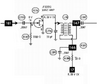
The transmitter section as I understand it starts with a mixer (FET7) which output is the 27MHz sample to be amplified through to the antenna.

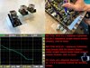
Im stuck at FET6 stage. I get a very very small signal (AC on Tx) out from L37 and reached the gate at FET6. At the drain the signal drops to be almost unnoticeable by the oscilloscope.

What I have done so far.
All DC voltages are ok on AM mode and TX mode.
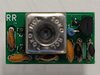
From the FET6 stage, all the components have been tested and tested good.
Even tested good, FET6 got replaced, problem persists.
C187, C189, C225, C236, (all ceramic) along with all resistors were removed and individually tested, tested ok
I have no way to test L36 other than measure continuity, which tests ok (having voltage on FET6 drain confirms)

My request to the forum is.
Can somebody will share their AC RMS voltage measures at points 181, 146 and 147?
Is its expected a lower voltage reading from the drain at FET6 than the gate? a low output impedance can explain that. The pre-driver stage TR45 seems to be a very very low input impedance amp.

Please help
 

Attachments

  • Transmitter Section.png
    Transmitter Section.png
    339.3 KB · Views: 18
  • FET6 XMIT AMP.png
    FET6 XMIT AMP.png
    38.9 KB · Views: 16

Is the signal reaching the gate of FET6 really your 27 MHz channel? Or is it some other frequency that L36 really isn't meant to work with?

Just seeing a voltmeter reading at the output of a mixer stage doesn't tell you enough to work with. Too many possible output frequencies. And if the frequency you want isn't one of them, you may still get a signal-voltage reading. Just not a helpful reading.

I would start with a receiver on the same channel, and the RF Gain set to keep the S-meter below middle scale. Might have to plug a coax jumper into it, thread the sleeve back over the cable and use the center pin as a "sniffing" antenna. Peak L39 and L37 for max S-meter reading, turning the RF Gain down as the signal level improves. Eventually there should be enough to see on a wattmeter.

And if you can't get a peak (or any signal) on the monitor receiver, the mixer stage is on strike. Or one of its two inputs is missing.

73
 
I’m not familiar with this radio but does it share any Cybernet board qualities?
 
I'm used to thinking of Cybernet's and Uniden's design habits as distinct.

Then again, both radios share a similar sort of block diagram. More, I would think because they do the same thing than for any other reason.

But Uniden didn't use Motorola-licensed PLL chips like the PLL02A. And Cybernet didn't use NEC or Fujitsu PLLs that I remember. But both vendors used Toshiba audio chips. Just not the same ones.

Different habits.

73
 
  • Like
Reactions: tecnicoloco
I'm used to thinking of Cybernet's and Uniden's design habits as distinct.

Then again, both radios share a similar sort of block diagram. More, I would think because they do the same thing than for any other reason.

But Uniden didn't use Motorola-licensed PLL chips like the PLL02A. And Cybernet didn't use NEC or Fujitsu PLLs that I remember. But both vendors used Toshiba audio chips. Just not the same ones.

Different habits.

73
I remember working on a Telestat that used the Cybernet VCO section that had that crappy epoxy encased part. The symptoms the OP mentioned reminded me of that exact problem the Telestat had.Razor radio made a replacement part for that epoxy encased part
 
Yes similar to those
96A842DA-8D2E-4D97-B725-902A143690CF.jpeg
 

Attachments

  • F1A5C36D-319A-470C-8535-DACEF4DDB7CD.jpeg
    F1A5C36D-319A-470C-8535-DACEF4DDB7CD.jpeg
    304.3 KB · Views: 5
  • 7A2DDD12-6125-4C74-AA82-91E4E4B2AE35.jpeg
    7A2DDD12-6125-4C74-AA82-91E4E4B2AE35.jpeg
    79.5 KB · Views: 4
  • 4D9AD1CF-7750-4672-9901-071ECAEF5D5B.jpeg
    4D9AD1CF-7750-4672-9901-071ECAEF5D5B.jpeg
    148.2 KB · Views: 5
Yes, the frequency at FET6 is correct and can be seen by a reciever next to it. But no measurable rf output from it. I'm not sure what should be the voltage at the gate or drain should be. Having that will be a great help
 
L36, the tiny toroid that FET6 drives into is incredibly fragile. So long as you have 8 Volts on the drain of FET6, and also at the spot labeled "147", It's probably okay. And if one leg of it has become an open circuit, you'll see zero Volts on one of those.

73
 
  • Like
Reactions: tecnicoloco
Unit_399 thanks for the snapshot. However those are the DC values which are ok on my radio.

I need the AC signal Voltage that I should have there. I have a very low voltage 27MHz signal at the gate and almost nothing in the drain. DC is ok. So it is a mystery for me.
 
I added my current voltage readings. RF Voltage as Vpp in red and Vdc in green. Im stuck at this time and really want this radio to come back to life. All help appreciated.

upload_2021-5-31_17-24-37.png
 
You didn't list the DC voltage at the source terminal of FET7. This would tell us if it's drawing any DC current.

Potentially important.

FET6 appears to lose half the signal on its gate terminal with only half as much on its output as its input. But the drive level into FET6 should be four or five times as much as shown.

One of the thirty-buck chinesium transistor testers from fleabay would tell you if FET6 has failed.

73
 
  • Like
Reactions: WP4AFB
My question here is, should I expect higher voltage at the drain of fet6? At least higher than the gate?

Next time I'll get the source of FET7. On that stage is weird the difference on g1 and g2 voltages, I would expect similar voltages, but it seems to be working fine.

I replaced FET6 with same results. I'll check the pin designation to match the schematic. I believe I'll remove it and measure with a needle ohmmeter at least to ensure who is the gate and which ones are source and gate to compare with the FET spec sheet.
 

dxChat
Help Users
  • No one is chatting at the moment.
  • @ Wildcat27:
    Hello I have a old school 2950 receives great on all modes and transmits great on AM but no transmit on SSB. Does anyone have any idea?
  • @ ButtFuzz:
    Good evening from Sunny Salem! What’s shaking?
  • dxBot:
    63Sprint has left the room.
  • dxBot:
    kennyjames 0151 has left the room.