• You can now help support WorldwideDX when you shop on Amazon at no additional cost to you! Simply follow this Shop on Amazon link first and a portion of any purchase is sent to WorldwideDX to help with site costs.

valve amp electrocution question

fodendaf

Active Member
May 2, 2009
416
52
38
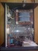
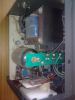
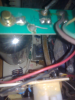
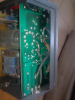
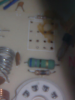
hi all. the relay in this amp seems to be corroded as the receive drops out occasionally and seeing as how I've often been warned of the high voltage in these i wonder could anyone mark on an image where to discharge the high voltage with a screwdriver on this amp. i need to pull the valve to reach the relay and order a replacement.
the amp is a synchrotron bv131s similar to the zetagi bv131.
 

Attachments

  • Amp1.png
    Amp1.png
    418.7 KB · Views: 779
  • Amp2.png
    Amp2.png
    394.9 KB · Views: 386
  • Amp3.png
    Amp3.png
    400.6 KB · Views: 481
  • Amp4.png
    Amp4.png
    385.5 KB · Views: 560

Reply to amplifier Hi_Voltage

First off always think SAFETY.

1) UN-Plug it for 24 hours.

2) wear rubber soled shoes.

3) carefully remove the top.

4) if you are right handed put your left hand in your back pocket, so as not
to allow a path through your body just in case you make a mistake.

5. beg or borrow a hi-voltage shorting stick from someone

Always think safety as the voltage can kill with only one contact.

6) short the top of the tube first, then those two large caps to the left of
the transformer in your pic.

7) do # 6 again, maybe two or three more times.

8) short the top of the tube again

At this point you should be safe

If you still feel reservations do everything again.....

You forgot to tell him not to allow any part of his right arm to touch the cabinet in any way as that creates a dc path to ground also?

As for the rubber soled shoes that is to keep your feet from fusing to the floor if you fail to follow any of these instructions and should not give a false sense of security.
 
short the top of the tube to where? the amp case? do you mean the copper cap for the valve top?. the amp has been unplugged for three months. I shorted the caps already. they are two 400volt caps that look to be in series. I shorted them in series and individually with hookup wire at the back of the circuit board.
 
Yes the top of the valve, short all locations to the case/cabinet then check with a vom to be sure they are dead.
 
thanks for all help so far.
I found a burned resistor labelled R1 between the tube socket and the relay the first colour is blue with a gold tolerance. It is in parallel with a green thing(possibly inductor) which is blue, light purple, black, gold
I found this thread about the same problem
http://bfreebandingtalktheplanet.runboard.com/t3043
but in the photo in that thread there is no inductor, just one 330ohm resistor.
so does anyone know or can calculate what value to install there or should I just pull the inductor and put in one 330ohm 5 watt resistor instead.
the ceramic disk capacitor in parallel with R1 is labelled 106k and C4
 

Attachments

  • Image008.png
    Image008.png
    169 KB · Views: 576
thanks for all help so far.
I found a burned resistor labelled R1 between the tube socket and the relay the first colour is blue with a gold tolerance. It is in parallel with a green thing(possibly inductor) which is blue, light purple, black, gold
I found this thread about the same problem
http://bfreebandingtalktheplanet.runboard.com/t3043
but in the photo in that thread there is no inductor, just one 330ohm resistor.
so does anyone know or can calculate what value to install there or should I just pull the inductor and put in one 330ohm 5 watt resistor instead.
the ceramic disk capacitor in parallel with R1 is labelled 106k and C4


that looks like 670 ohms . blue , violet, black , gold is the tolerance 5%
 
I am going to replace the 4PDT relay with a new one because I know another man with the same amp that sanded the corrosion off the contacts on his bv131 and the problem reoccurred.
I might replace the burned resistor if I knew what value to replace it with as its markings are burned off. That is not so critical to me as I understand its function is filtering and will not damage the amp as is.
I opened the relay up and I see only one of the contacts is burned. I wonder if I hook another relay in parallel with the stock relay is there any chance of damage occurring to the amp or radio? All I need is a single pole single throw relay and I have several here.
 
Last edited:
On those amps, after you discharge HV on tube and caps, I always leave a clip on the anode to ground. Sometimes those caps just seem to build up a charge. So putting jumper from anode to ground willalleviate this. Just make sure you disconnect before you plug in or you will have other problems.
 
  • Like
Reactions: 3 people
If the relay is burned just replace it. Substituting an spst relay for one of the contacts isn't a very good idea. That resister isn't a 'filter', but is regulating either voltage or current. If you don't have a schematic for that amplifier you can only guess what it's purpose is. I'd really try to find a schematic.
- 'Doc
 
I remember a cber back in the 70s getting electrocuted....he was sitting back in his chair and noticed a tube was crooked in his big linear and he reached over and was gonna push it straight with his finger and it light him up...knocked him right out of his chair....they found him all balled up in the corner of the room smoking....dead as a wedge.:eek:
 
i have the relay ordered so I should have it in a few days. I read on the net that I can scrape the carbon off the resistor and measure the resistance from both sides of the break and work it out that way so all in all I think i'm not doing too badly. Thanks to all who responded and I believe I answered all the questions directly or indirectly in the body of my posts.
 
I remember a cber back in the 70s getting electrocuted....he was sitting back in his chair and noticed a tube was crooked in his big linear and he reached over and was gonna push it straight with his finger and it light him up...knocked him right out of his chair....they found him all balled up in the corner of the room smoking....dead as a wedge.:eek:

My dad lost several finger and toe nails from an sb-220
 

dxChat
Help Users
  • No one is chatting at the moment.
  • dxBot:
    Tucker442 has left the room.
  • @ BJ radionut:
    LIVE 10:00 AM EST :cool:
  • @ Charles Edwards:
    I'm looking for factory settings 1 through 59 for a AT 5555 n2 or AT500 M2 I only wrote down half the values feel like a idiot I need help will be appreciated