Just because you can doesn't always mean you should. Unless it's for a paying customer. The owner of this Varmint XL1000 has been a customer for 40-plus years, so telling him "NO" is not one of my bad habits. Besides, he's willing to pay what it costs.
When someone asks about rehabilitating a Varmint XL1000 base amplifier I generally answer "You can't afford it". It has three "baldie" tubes driving six 12-pin 6LF6/6KD6 type tubes. If you were to pay the average price for those nine tubes you could buy a decent solid-state base amplifier.
Fortunately for this customer he has a decent supply of tubes. Good thing, since I refuse to sell the sweep-type tubes. I don't like to sell anything I can't afford to stand behind if there's a problem down the line. And yes, it took more than the first nine tubes he came up with. Several of the driver tubes flunked on our tester.
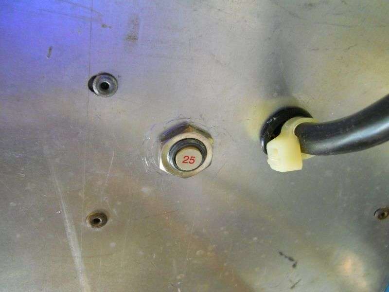
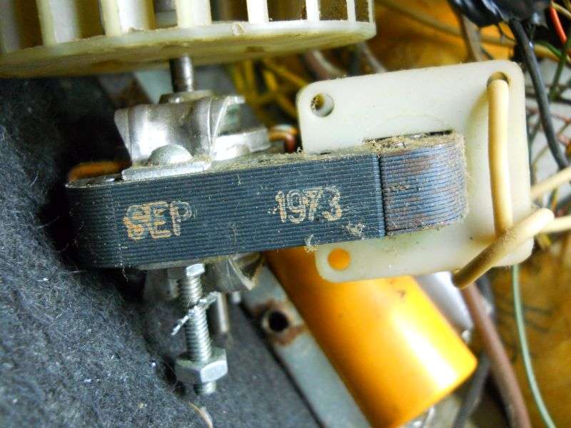
One issue to remember is age. This one probably wasn't built the same year this fan is dated, but can't be much newer.
One of the best reasons to turn down this kind of repair is the accumulated decades of shoddy or incompetent repair attempts.
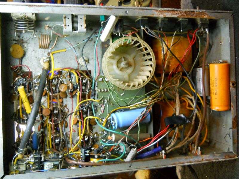
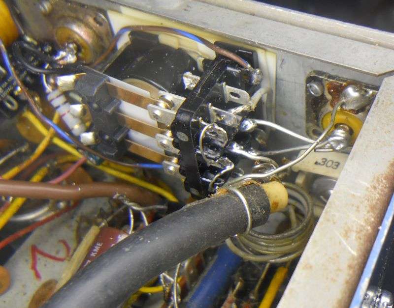
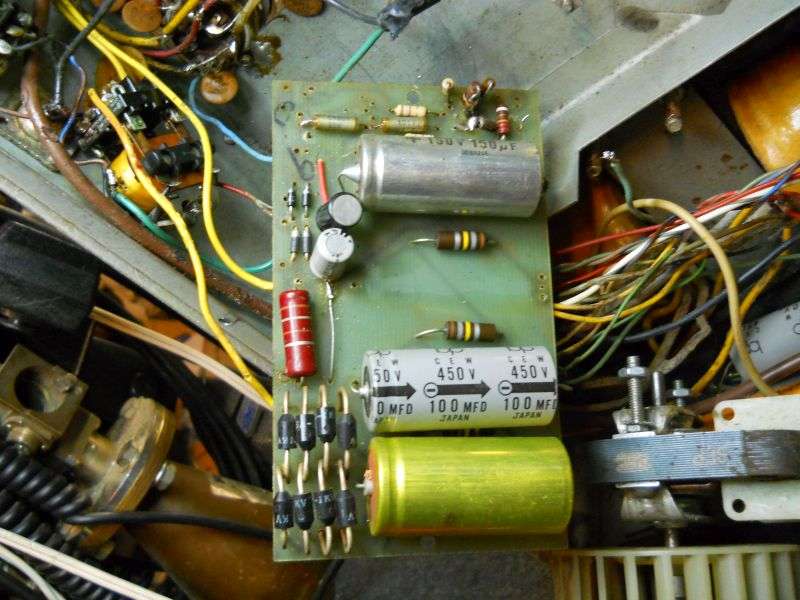
This model has most of the 'works', power supply, bias and keying circuits on a printed circuit board underneath. The component side is facing away from you, and there is neither a schematic diagram nor a layout showing where parts are placed. That, and the condition of this one makes replacing all the circuits on it the only viable path to making it useable again.
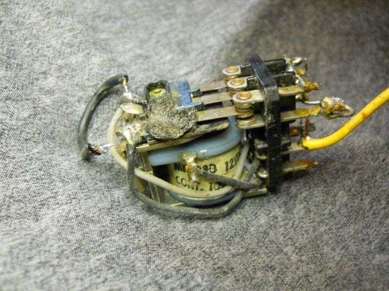
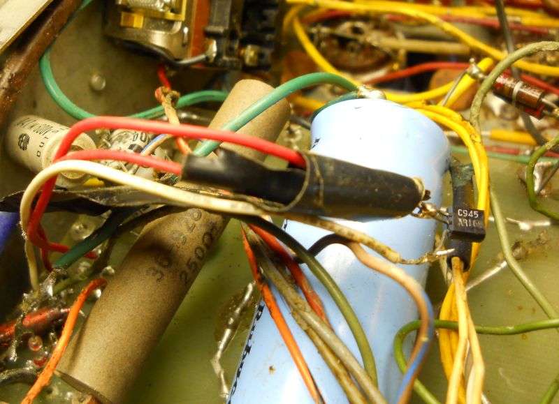
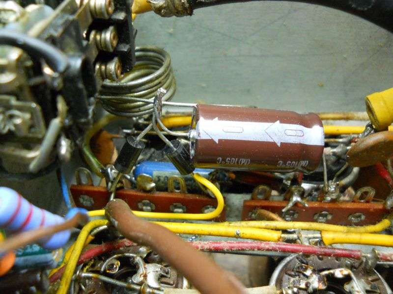
Everybody and his in-laws have been in this one. My favorite custom feature is this keying transistor on long lead wires, wrapped tastefully in black electrical tape. I never cared for pulling out this pc board to replace parts, but whoever did this really, really didn't want to.
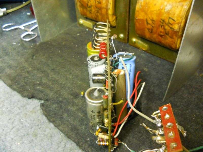
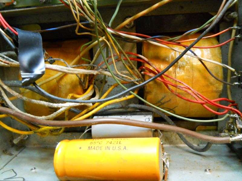
The three 100uf high voltage filter capacitors on the circuit board are augmented by another string of three bolted to the chassis side rail under the two power transformers. They will get removed and replaced with a series string of three 220uf caps.
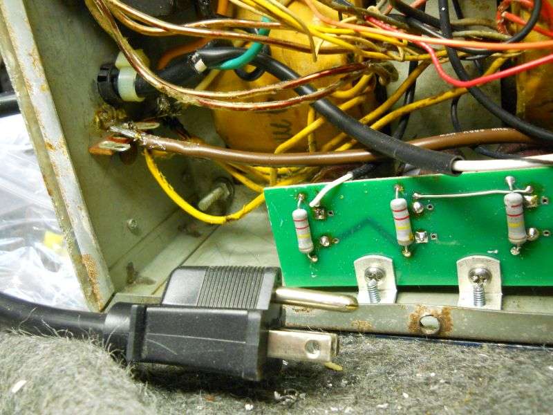
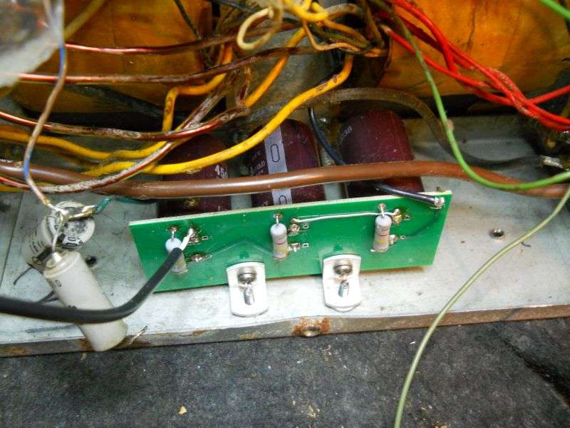
This is the "Maco filter" board we sell on fleabay. Works fine in this model to replace the six 100uf caps it was built with.
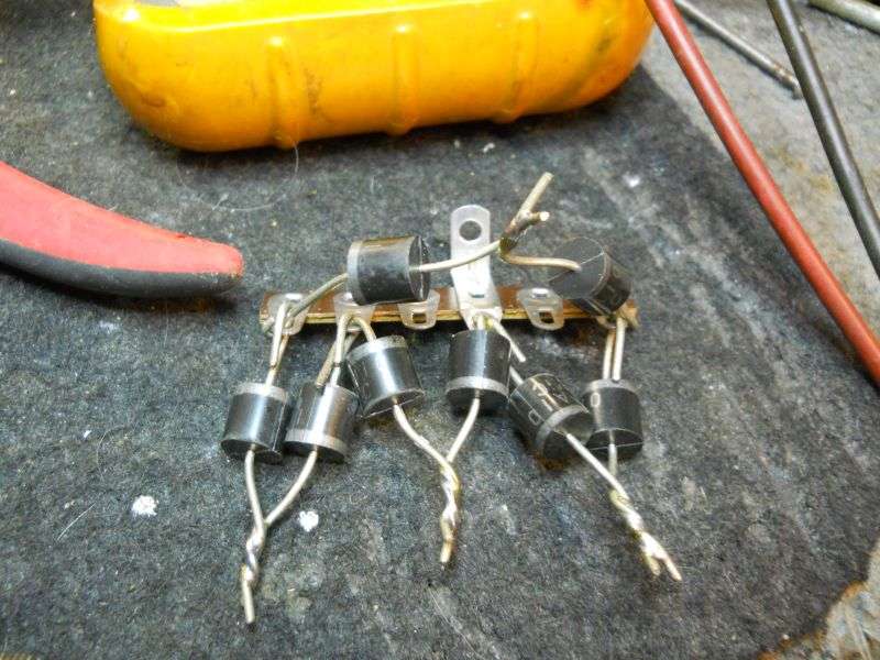
The circuit board had a full-wave bridge rectifier for the high voltage that used eight 1N5408 3-Amp rectifier. This replacement bridge is ugly, but uses the so-called "10-Amp" rectifiers. They look just like the 6-Amp parts, but the added safety margin can't be a bad thing.
The original setup had a switch on the front panel marked "High/Supermod". This uses a quirky circuit that kept getting changed from one production run to the next. Even so, this one gets a modified version of that feature.
It's in the center of the space in the center underside where the circuit board used to be. The 12-Volt relay supply is up against the rear panel at the top of this pic. The high-voltage rectifier bridge is still ugly on the bottom, and the stuff in the middle here puts a negative bias voltage onto the final tubes' grid circuits.
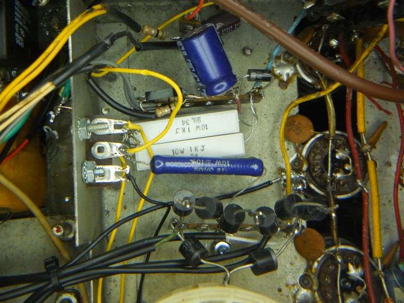
The driver tubes get their own separate bias source. One rectifier taps off the 6.3-VAC heater power and charges the 4700uf cap. The second diode isolates this filter cap from the driver tubes' grid circuit. This keeps any rectified "grid leak" voltage from charging up that fat filter cap.
Never assume that any one thing in a linear this old is still okay to use. This one got a new power switch. The old was badly tortured and beginning to cut out.
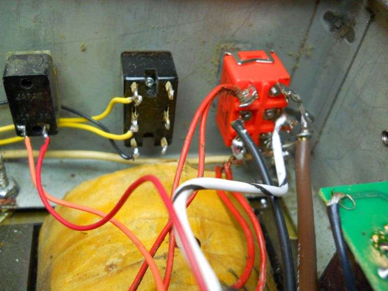
The original power cord had a plug that contained two glass fuses. This was a clever idea, but two-prong cords are just a bad idea for the most part. A circuit breaker got mounted on the rear panel, along with a 3-prong cord and plug.
There's more, but I'll have to finish this later on. It's my beditme.
73
When someone asks about rehabilitating a Varmint XL1000 base amplifier I generally answer "You can't afford it". It has three "baldie" tubes driving six 12-pin 6LF6/6KD6 type tubes. If you were to pay the average price for those nine tubes you could buy a decent solid-state base amplifier.
Fortunately for this customer he has a decent supply of tubes. Good thing, since I refuse to sell the sweep-type tubes. I don't like to sell anything I can't afford to stand behind if there's a problem down the line. And yes, it took more than the first nine tubes he came up with. Several of the driver tubes flunked on our tester.
One issue to remember is age. This one probably wasn't built the same year this fan is dated, but can't be much newer.
One of the best reasons to turn down this kind of repair is the accumulated decades of shoddy or incompetent repair attempts.
This model has most of the 'works', power supply, bias and keying circuits on a printed circuit board underneath. The component side is facing away from you, and there is neither a schematic diagram nor a layout showing where parts are placed. That, and the condition of this one makes replacing all the circuits on it the only viable path to making it useable again.
Everybody and his in-laws have been in this one. My favorite custom feature is this keying transistor on long lead wires, wrapped tastefully in black electrical tape. I never cared for pulling out this pc board to replace parts, but whoever did this really, really didn't want to.
The three 100uf high voltage filter capacitors on the circuit board are augmented by another string of three bolted to the chassis side rail under the two power transformers. They will get removed and replaced with a series string of three 220uf caps.
This is the "Maco filter" board we sell on fleabay. Works fine in this model to replace the six 100uf caps it was built with.
The circuit board had a full-wave bridge rectifier for the high voltage that used eight 1N5408 3-Amp rectifier. This replacement bridge is ugly, but uses the so-called "10-Amp" rectifiers. They look just like the 6-Amp parts, but the added safety margin can't be a bad thing.
The original setup had a switch on the front panel marked "High/Supermod". This uses a quirky circuit that kept getting changed from one production run to the next. Even so, this one gets a modified version of that feature.
It's in the center of the space in the center underside where the circuit board used to be. The 12-Volt relay supply is up against the rear panel at the top of this pic. The high-voltage rectifier bridge is still ugly on the bottom, and the stuff in the middle here puts a negative bias voltage onto the final tubes' grid circuits.
The driver tubes get their own separate bias source. One rectifier taps off the 6.3-VAC heater power and charges the 4700uf cap. The second diode isolates this filter cap from the driver tubes' grid circuit. This keeps any rectified "grid leak" voltage from charging up that fat filter cap.
Never assume that any one thing in a linear this old is still okay to use. This one got a new power switch. The old was badly tortured and beginning to cut out.
The original power cord had a plug that contained two glass fuses. This was a clever idea, but two-prong cords are just a bad idea for the most part. A circuit breaker got mounted on the rear panel, along with a 3-prong cord and plug.
There's more, but I'll have to finish this later on. It's my beditme.
73
Last edited: