There has been some repeated interest in homebrewing a suitable dipole for vertical use on several forums and numerous threads. I decided to put this info up so a forum seach could take them directly to this method of getting on the air with an easy to make, pole mountable, rigid version of the vertical dipole.
I hope it helps.
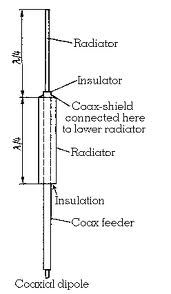
If you want a vertical dipole then:
1. get two 1' pieces of PVC with sufficient diameter to insert an aluminum tube into.
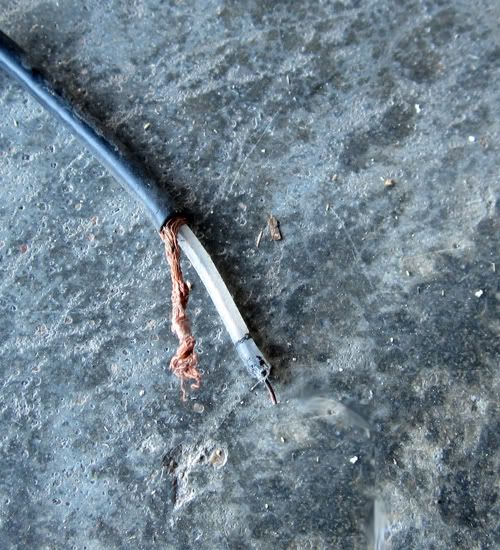
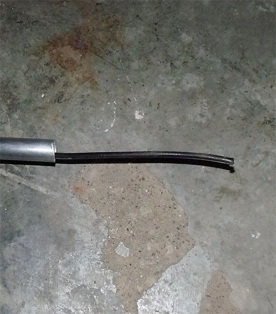
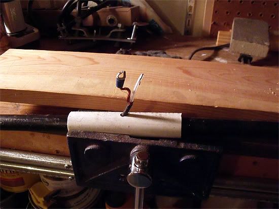
2. cut the end off of a coax feedline and separate the braid from the center for about two inches.
3. put this prepared end of the coax all the way through one of the 1' PVC nipples
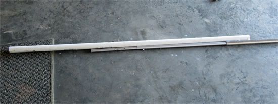
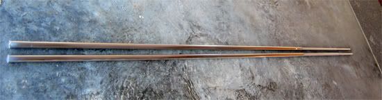
4. cut both of the tubes of aluminum to 8' 7" length.
5. push the prepared end of the coax all the way through one of the aluminum tubes.
6. this results in the PVC nipple and one of the tubes sharing the coax through them, so now insert the aluminum tube into the PVC nipple for at least six inches and secure them to each other with a short self-drilling screw.
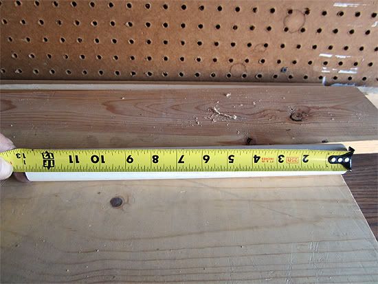
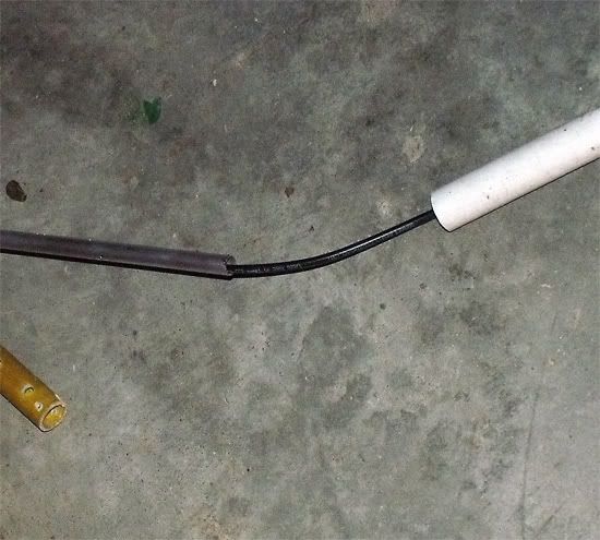
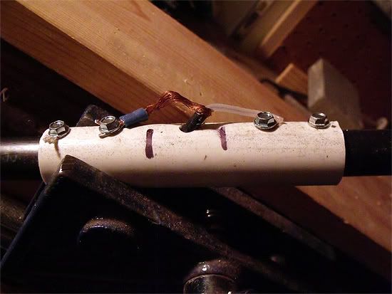
7. take the second PVC nipple and drill into the side of it exactly in the middle a 1/4" hole, or one large enough to feed the coax through.
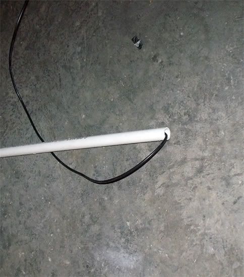
8. push the coax into one end of the PVC nipple and pull it out of the nipple through the hole you drilled into the side.
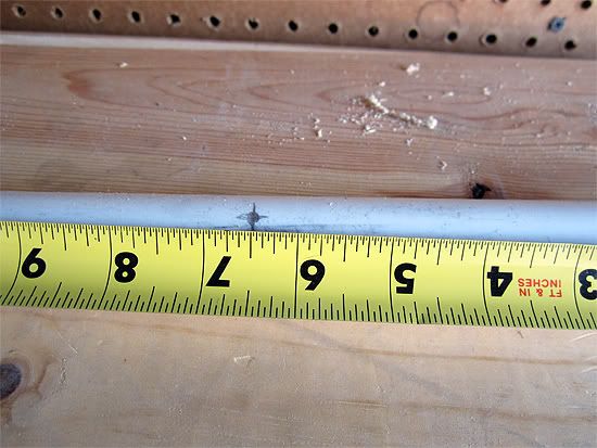
9. Push the nipple onto the Aluminum tube 5.5" deep.
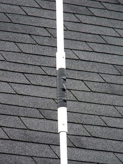
10. You should now see your prepared end of the coax sticking out the hole in the side of the PVC nipple. Press the other aluminum tube into the PVC nipple for a distance of 5.5". Secure both tubes with short self-drilling screws.
11. Now take the prepared end of the coax that is sticking out through the center PVC nipple and fasten them into the ends of the two aluminum tubes with short self-drilling screws through the center PVC separator/insulator.
12. Take either silicone, tape, or heat shrink and place it on/over the coax to dipole connection for weather-proofing. Optionally you may cap the end of the dipole which has no PVC insulator on it. This is the top.
13. Where the coax comes out of the bottom tube/PVC insulator make a coax choke of 4" - 5" diameter x 5/6 wraps.
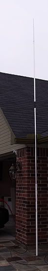
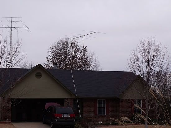
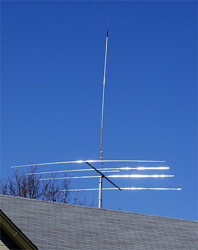
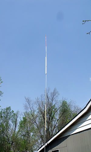
The bottom PVC insulator provide a means of mounting the dipole to a mast. If more sturdy mounting than the PVC provides is needed you can wrap the PVC with fiberglass, or use an old fiberglass shovel handle instead. I've done both. If the dipole needs tuning as it may be too long by a little due to its diameter trim from both ends of the aluminum tubes as you would any wire dipole.
I hope it helps.
If you want a vertical dipole then:
1. get two 1' pieces of PVC with sufficient diameter to insert an aluminum tube into.
2. cut the end off of a coax feedline and separate the braid from the center for about two inches.
3. put this prepared end of the coax all the way through one of the 1' PVC nipples
4. cut both of the tubes of aluminum to 8' 7" length.
5. push the prepared end of the coax all the way through one of the aluminum tubes.
6. this results in the PVC nipple and one of the tubes sharing the coax through them, so now insert the aluminum tube into the PVC nipple for at least six inches and secure them to each other with a short self-drilling screw.
7. take the second PVC nipple and drill into the side of it exactly in the middle a 1/4" hole, or one large enough to feed the coax through.
8. push the coax into one end of the PVC nipple and pull it out of the nipple through the hole you drilled into the side.
9. Push the nipple onto the Aluminum tube 5.5" deep.
10. You should now see your prepared end of the coax sticking out the hole in the side of the PVC nipple. Press the other aluminum tube into the PVC nipple for a distance of 5.5". Secure both tubes with short self-drilling screws.
11. Now take the prepared end of the coax that is sticking out through the center PVC nipple and fasten them into the ends of the two aluminum tubes with short self-drilling screws through the center PVC separator/insulator.
12. Take either silicone, tape, or heat shrink and place it on/over the coax to dipole connection for weather-proofing. Optionally you may cap the end of the dipole which has no PVC insulator on it. This is the top.
13. Where the coax comes out of the bottom tube/PVC insulator make a coax choke of 4" - 5" diameter x 5/6 wraps.
The bottom PVC insulator provide a means of mounting the dipole to a mast. If more sturdy mounting than the PVC provides is needed you can wrap the PVC with fiberglass, or use an old fiberglass shovel handle instead. I've done both. If the dipole needs tuning as it may be too long by a little due to its diameter trim from both ends of the aluminum tubes as you would any wire dipole.