B

You are using an out of date browser. It may not display this or other websites correctly.
You should upgrade or use an alternative browser.
You should upgrade or use an alternative browser.
-
You can now help support WorldwideDX when you shop on Amazon at no additional cost to you! Simply follow this Shop on Amazon link first and a portion of any purchase is sent to WorldwideDX to help with site costs.
natural asymmetrical voice modulation
Try this link Seems some voices have more or less symmetry. Explains why some voices cut through the QRM better than others. I have used mike phasing and modulator phase reversal for improved audio density on AM with a plate modulated Transmitter. It does provide improvement.
RCB
Amplitude Modulation
The AM Forum - Index
Amplitude Modulation and PEP by Bacon,WA3WDR
http://forums.qrz.com/archive/index.php/t-23147.html
www
And a question.
If I wanted to use mic phasing and modulator phase reversal for improved audio density on AM with a plate modulated transmitter, is there a very simple means of doing so without specific equipment to determine that phasing and phase reversal?
And...
Is a plate modulated transmitter required for this to work?
Curious...
- 'Doc
Simple way to change mike phase, reverse the leads on the mike elementAnd a question.
If I wanted to use mic phasing and modulator phase reversal for improved audio density on AM with a plate modulated transmitter, is there a very simple means of doing so without specific equipment to determine that phasing and phase reversal?
And...
Is a plate modulated transmitter required for this to work?
Curious...
- 'Doc
while looking on a scope for the most positive modulation peaks.
With a plate modulated TX swaping the plate cap leads on the modulator tubes.
RCB
So there isn't a simple/easy way of doing this. I can't say that the average person is very likely to own an 'O'-scope, so there's no way for that average person to do it. In other words, while it may be 'do-able', it's a 'specialized' thingy, it isn't commonly done. Hell of a difference between 'possible' and 'practical'. And a far cry from proving it's the 'best' way of doing it.
- 'Doc
- 'Doc
what is "asymmetrical modulation" ?
connect an AM transmitter to a scope and feed a 30mv. 1khz. tone into the mic. input and look at the scope. with respect to the ensuing pattern you can flip it, slide it or turn it and the "shape" of the pattern remains the same.
that's a symmetrical signal. the pattern is a sinusoid.
you have exact correspondence of form and constituent configuration on opposite sides of a dividing line or plane. (the X & Y axis' of the scope)
symmetrical modulation types include but are not limited to FM, CW, MCW and FSK.
repeat the test again with the human voice. that's an asymmetrical signal, the pattern being anything but sinusoidal.
asymmetrical modulation types include but are not limited to AM, DSB and SSB.
Last edited:
freecell,
what is your opinion of compressing the negative peaks of an AM signal so they cant exceed 100% and allowing the positive peaks to exceed 100%?
LC
what is your opinion of compressing the negative peaks of an AM signal so they cant exceed 100% and allowing the positive peaks to exceed 100%?
LC
freecell,
what is your opinion of compressing the negative peaks of an AM signal so they cant exceed 100% and allowing the positive peaks to exceed 100%?
LC
That is exactly what is done in commercial broadcasting on the AM band. The negative peaks are limited to 100% while the posiotive peaks are allowed to achieve 125% peak modulation. The result is louder audio without exceeding 100% neg modulationand the resulting splatter.We used a Gates Solidstatesman limiter/amp in the audio chain that had a detector that would ensure the positive peaks were always the dominant peaks and would automatically reverse polarity if it needed to in order to achieve the desired result.
a 100% negative peak = 0, so how can it exceed zero/100% - modulation? the modulation is already turned off.you can't turn it off anymore than off.
all you will achieve is turning the carrier off and introducing distortion.
thats like trying to turn a bulb onto negative brightness.
whats wrong with just having 100% or close too it positive modulation?
it sounds far better/clearer than any form of compression or overmodulation.
all you will achieve is turning the carrier off and introducing distortion.
thats like trying to turn a bulb onto negative brightness.
whats wrong with just having 100% or close too it positive modulation?
it sounds far better/clearer than any form of compression or overmodulation.
Last edited:
a 100% negative peak = 0, so how can it exceed zero/100% - modulation? the modulation is already turned off.you can't turn it off anymore than off.
thats like trying to turn a bulb onto negative brightness.
Sure you can exceed more than 100% neg mod. 100% is exactly the amount needed to fully and properly modulate a carrier. Any more than what is required is more than 100%. When that happens tha carrier is turned off for a slight amount of time and then back on. This results in lots of modulation byproducts that appear as distortion.
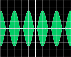
The following are taken from www.nu9n.com/am.html and show the various waveforms of differing levels of AM modulation.
Remember that it is the neg peaks that cause the distortion and overmodulation not the positive peaks. The pos peaks add "loudness" to the signal. It has worked for decades in the commercial broadcast industry where low distortion is a must.I once tested a Nautel transmitter at 100%neg and 220% pos modulation when I had modulator troubles. It looked pretty cool on the 'scope and man the sucker was LOUD but clean but I did not dare put it into the antenna system. The legal limit here is 125% pos peak mod.
Figure 3
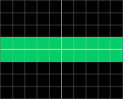
Scope Calibrated for +1 and -1 Divisions
With Full Unmodulated Carrier Applied
Figure 4
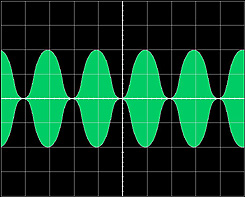
AM at 100% Symmetrical Modulation
Figure 5
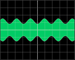
AM Undermodulated
Figure 6a
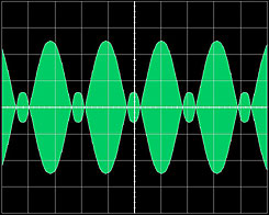
AM Overmodulated (Low-Level)
Figure 6b
AM Overmodulated (High-Level)
Figure 6c
AM Asymmetry - Correct Phase (Pos 110%, Neg 95%)
Figure 6d
AM Asymmetry - Inncorect Phase (Pos 95%, Neg 110%)
I think NU9N got the overmodulated labels for low-level and high-level backwards.
High-level is where modulation power is applied to the DC power of the final(s). Also known as "plate modulation".
Low-level is where modulation is applied before the final amplifier and then amplified by linear devices.
When you over-modulated on a high-level design, the output signal will appear as double-sideband reduced carrier, but not splattering.
Its the low-level design that splatters on >100% negative peaks.
I think NU9N got the overmodulated labels for low-level and high-level backwards.
High-level is where modulation power is applied to the DC power of the final(s). Also known as "plate modulation".
Low-level is where modulation is applied before the final amplifier and then amplified by linear devices.
When you over-modulated on a high-level design, the output signal will appear as double-sideband reduced carrier, but not splattering.
Its the low-level design that splatters on >100% negative peaks.
I took his high-level low-level thing to be slight overmodulation and severe overmodulation. I worked for 22 years with high level plate modulated AM transmitters and when they are grossley overmodulated the carrier gets cut off for an appreciable amount of time and splatter is pretty bad.It happens all the time when an RF tube fails and the modulators keep on pumping all that audio with just one RF tube that is still working.
I realise it may be labelled as modulation levels greater than -100%,i have seen those scope pictures both there and in other places,
the point i was making was it technically only stops the carrier/modulation for a time relative too the percentage it is over -100% modulation and causes crossover distortion,it doesn't actually modulate anything.seeing as the carrier is already stopped,except for in certain cases of low level AM where it generates a dsb suppressed/reduced carrier signal,in which case it would still technically be modulating.
the term greater than -100% modulation is very misleading,its like trying to quantify something that in most cases doesn't exist.unless you classify turning the carrier off as modulation.
I see what you mean about the greater than 100% neg mod figure.To be honest I have never in my career heard a referance to any level greater than 100% neg mod.It is always refered to as "exceeding 100% neg modulation" with no such quanitative figure attached to it.The greater the over mod the longer the period of time the carrier is cut off and the worse the splatter.
dxChat
- No one is chatting at the moment.
