• You can now help support WorldwideDX when you shop on Amazon at no additional cost to you! Simply follow this Shop on Amazon link first and a portion of any purchase is sent to WorldwideDX to help with site costs.

Wow, this cobra 2000 brings back memories...

Hawkeye351

Well-Known Member
Jun 27, 2021
488
354
73
56
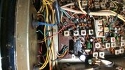
On the desk is a first generation Cobra 2000 GTL.

Reason for visit:
No xmit, no receive...

Upon opening the cover, it hit me. This was the very first cobra 2k I ever worked on back in 1997. The owner back then bought it brand new along with a new expo kit and brought it straight to me. I contacted the owner and inquired about this radio, the current owner told me it was his father's and hes now passed away. He stated he remembered his dad always loved that radio and kept my handle stamped on his desk beside the radio. After his passing, his son got into the radio and heard I was the best around for 2ks and such, so he got it to me through a friend. I never knew who he was.

He said no one but me has ever been inside that radio, which I verified after looking it over (I remember my old school stupid work, lol). I feel honored to be the only person to ever touch this old classic from brand new to now.

Upon evaluation:
TR24 limiter removed (I was young and dumb at that time).

R131 clipped (again, I was young and dumb at the time).

R174 removed, jumper installed.

Slide choke 5.6uh off D52 (?, strange).

Sloppy solder, lol...

Expo kit installed next to headphone jack in front (again, I was young and dumb at that time).

Has original 1306 driver, 1307 final.
R183 is 12 ohm

Issues:
PLL pins 7,8,9 eaten off by glue damage.
10.240mhz crystal leg eaten off by glue.
Torodial coil next to pre-driver glue damage.
2 disc caps in 1st IF bad from glue on legs.
Both meters stuck.
All controls scratchy.
Cobwebs all inside.

What I'm gonna do:
1.Replace "10v blues" caps and a few others that are known to go bad in these rigs, upgrade if needed.
2. Straighten out the strapped clarifier.
3. Replace PLL and 10.240 crystal, along with other glue damaged parts.
4. Replace the limiter, resolder R131.
5. Replace passthrough (1135) and PS reg (1419) with 6487G.
6. Regrease all chassis mounted components.
7. Unstick meters, replace if needed.
8. Clean all controls, replace if needed.
9. Install variable key on RF Gain control.
10. Replace meter lights with bright LEDs.
11. Complete alignment.
12. Thorough cleaning, inside and out.

I leave anything out you guys/gals? I want this one perfect, it has a lot of sentimental value not only to the current owner, but myself also.
 

Well, got everything back to factory.
Transmit and receive is back up.
Only issue is the frequency stays on 25.765 with channel knob turned anywhere. That's on 2 external frequency counters.

Replaced MB8734 with MMB8719
Replaced JP35 and L18 at the edge of the PLL.
Replaced 10v caps.
Checked voltage reg (3756), all voltages correct.
Checked for 8v on the 1000uf cap at the end of the PLL, 8.17v present.
No voltage on pin 9 of pll.
Replaced 10.240mhz crystal due to glue.
Vco voltage correct.
Can't do alignment till I figure out this frequency issue.

Note:
After turning on, you must turn channel knob either way several times before it kicks in to xmit. Also, the back edge of the channel encoder board gets extremely hot.

Any ideas?
 
Only things on the channel selector board are the selector and some resistors for the LEDs in the channel display. Is it possible there's a short in the channel selector itself? Or maybe somewhere else and it's trying to pull too much current through the channel selector? Admittedly I'm guessing here, but there's just not much to fail on that board.
 
  • Like
Reactions: Hawkeye351
I may have the PLL in backwards.
I remember which way the 8734 came out, but not sure of pin configuration on this MM8719.

Any procedure for checking PLL?
Is the MMB8719 a direct pin match for the 8734? Should it be mounted opposite how the 8734 was oriented?

Xmits and receives great, but it is stuck on just 1 frequency (25.765mhz) no matter where you turn the channel to, also clarifier makes no change whatsoever.

Maybe this MMB8719 is bad, I yanked it out of a 148gtl st that wasn't working at all. How do I test this pll? How should the mmb8719 be oriented?
 
I don't have a procedure for checking out the PLL by itself, except to stick it in a known working radio and see if it stops working.

The MB8719 and MB8734 are almost exactly the same. Really, the MB8734 is just a modified MB8719 to keep the FCC happy. Easier on Uniden, too, since they didn't have to make huge changes to their board layout.

The chip should be oriented the same way for either part.

Here's a link to one of Lester's mods that shows the orientation better than I can describe it. Best one is near the bottom:
 
  • Like
Reactions: Hawkeye351
I notice the round indent on the corner of one end of the 8734 (which came out of it) is on the top right corner, but the mmb8719 round indent is on the bottom right corner.

I'll try to take a pick.
 
The pic is backwards due to my rear camera not working.

I have the 8734 laid across a filter in the orientation as it came out.

The mmb8719 is mounted, but not sure if I have it oriented the right way.
 

Attachments

  • 0525231858.jpg
    0525231858.jpg
    535.8 KB · Views: 13
It didn't register at first that you were typing MMB8719. My brain just dropped the first character to make it something familiar. Don't know who made that, but it wasn't Fujitsu. In this case, though, that just helps with figuring out the orientation.

That round indent on each of the chips is also of a different size and depth. Why Fujitsu put their indent where they did I'll never know. The indent at pin 1 like on your MMB8719 is far more common for DIP style chips. It's also got a notch at one end, which is also almost always next to pin 1. I think you've got it oriented correctly since it looks like pin 1 is far away from that big cap at the end of the chip.

So if that chip is dead, it's not because of the direction it was installed in the board.
 
  • Like
Reactions: Hawkeye351
Just checked voltages on pins 1 through 9 on the backside.
Pin 1 and 9 show exactly 8.17v
All others 2-8 show 7.2v
Does this sound about right?

I checked the 3754 reg also, voltages on it seem right.

Adjusting PLL Offset oscillators (L23, L22 and L59) make no change whatsoever.

L21 (2nd VCO Buffer) makes no change at all.

All 4 RF stage cans adjust smoothly and changes output as it should.

L20 (1st VCO Buffer) adjusts smoothly and changes result as it should.

VCO voltage adjusts just fine also.

So,
L21, L22, L23, L59 make no change at all when adjisting.
PLL pins 1 and 9 show 8.17v
PLL pins 2 - 8 show 7.2v
Pins 10 - 18 vary from 0v on 1 pin to 4.5v on another to 7.2v on another.

I may yank out the 2 remaining electrolytic caps in the VCO/PLL section and replace them. Beginning to believe all these caps in this one is shot. It's one of the first production lines of 2000 with the original 1306 driver and 1307 final.
 
Oh, and as you can tell in the above pic, it does still have an expo kit installed, that's why the 11.325mhz crystal is not in its spot. And no matter where you flip that expo, the frequency remains at 25.765mhz.
 
Ok, can you verify that the Pin for Pin for the Channel selector is working?

When you see 25MHz, that means the EXPO kit may be the problem - you'll need to restore the thing to stock, to recreate and fix the original condition.

So you'll need to verify that the Channel selector- and it's "locator" switch - the one that declares the input valid by following the detent - affects the lock pin too - pulls it up or lets it stay down when the channel selector is working and properly set the channels you're selecting.

The selector has a two-sided wafer sandwich so you'll have to verify the pin out are valid and working for the PLL to see and program the pins to get you your divisor output.
 
  • Like
Reactions: Hawkeye351
Just replaced the 4.7uf 25v cap in front of the VCO block.

Just replaced the 0.47uf 50v cap next to the 1000uf cap at the end of the PLL.

Same result, same frequency of 25.765mhz.

Yanked out expo and put original 11.325 Crystal back in its place.

Same result, same frequency of 25.765mhz.

Yanked out the strapped clarifier mod.

Same result, same frequency of 25.765mhz.

Completely unhooked clarifier.
Same result. Same 1 frequency of 25.765mhz.

Completely removed 11.325mhz crystal.
Same result of only 25.765mhz. Made no difference removing crystal.
 
Thanks Andy, I yanked out the expo and put 11.325 back in its place, same result.

Yanked out strapped clarifier mess, same result.

Completely removed clarifier wires from board, same result.

Completely removed the 11.325, same result with or without 11.325 and with or without strapped clarifier.

I'll have to figure out how to test the channel switch.
 
Ok, when you do, try to look at making the switch off the detent, and look at the LOCK pin -have to make sure that even though there is a pull up resistor off the Power feed to Pin 9 -Pin 6 can be allowed to fall to near Ground.

1685063889596.png

The Channel Selector has this...
1685064364106.png
See Pin 6? That's line test point #248 - which also goes to TR/Q 35 that TX inhibit switch. Pin 6 is buffered with power from 8V constant and whatever that channel selector is set.

Why is this coming up?

What you said earlier to get the thing to even TX You had to spin that channel knob to get it to wake up - that might be due to the detent switch affecting the lock pin - if it's dirty it's left floating and kinda wants to go, but doesn't' so it sees a frequency and locks into it.

So the test comes from how well the #248 line is held - low or high - well and stable enough so the thing can even stabilize and look for input on the pins to set the divisor.

But, if the 25MHz frequency is messing with the Counter - might want to use a separate CB or Amateur to tune as a Monitor Radio and see if anything can get heard thru that monitor.
 
  • Like
Reactions: Shadetree Mechanic

dxChat
Help Users
  • No one is chatting at the moment.
  • @ Wildcat27:
    Hello I have a old school 2950 receives great on all modes and transmits great on AM but no transmit on SSB. Does anyone have any idea?
  • @ ButtFuzz:
    Good evening from Sunny Salem! What’s shaking?
  • dxBot:
    63Sprint has left the room.
  • dxBot:
    kennyjames 0151 has left the room.