I have a Yaesu FT-101E (late model) that initially had both transmit and receive problems but I've since corrected the receive issues with a thourough cleaning of the RL-1 and RL-2 relays. Now it receives as it should and will key and unkey properly. During the tune up process no i.c. value displays on the meter and adjusting the bias potentiometer has no effect. The meter does properly respond on receive and will move complete right when ALC is selected during the tuning process. 176vdc is present on pin 3 of the output tube sockets and the heaters work. I'm not sure if this is still potentially a relay issue or if there is somewhere else I should be looking at. Any help would be greatly appreciated. Thanks!

You are using an out of date browser. It may not display this or other websites correctly.
You should upgrade or use an alternative browser.
You should upgrade or use an alternative browser.
-
You can now help support WorldwideDX when you shop on Amazon at no additional cost to you! Simply follow this Shop on Amazon link first and a portion of any purchase is sent to WorldwideDX to help with site costs.
-
A Winner has been chosen for the 2026 July 4th Retevis RA89R Giveaway! Click Here to see who won!
Yaesu FT-101E no transmit, no i.c.
- Thread starter Champo
- Start date
Replace the wax mica cap c13 coming off the driver with a new silver mica 1000v or better. 80 to 100 pf. It's on the bottom tucked under the edge of the case. I have had a few no output 101s and that cured it. That should be changed along with c125. They should always be changed on general principle as they are known weak links in these radios. If they short its a big headache. If they open not so much just no output.
Last edited:
Thank you for the advice. I will do that as a precautionary measure. Is there a good method for confirming that this is indeed the problem currently plaguing the rig? It is missing the HV on transmit. This was checked with driver and PA tubes out though so I'm not sure if that was an accurate test.
I would just replace them and see what you get. Also the relay , even though you have the receive back could still have some bad connections. The guy on ebay that sells the used ones tests them good so you should be ok buying a set from him. His name is 2tubes and a . Also there was another good seller Champstate. Believe it or not the original relay is still available directly from Yaesu but last I remember a few years back they were $125.00. They are NOS so once gone they are gone. If you had a mint mint 101 that you planned on keeping for the rest of your life I would say buy one just to have. But that's a lot of $ if it's just a so so radio you do not plan on keeping. I have a few matched sets of the Japan 6js6c tubes I collected over the years just incase. But now that I do not have 5 101s in the stable anymore I might pull them out and list a set or 2 for sale. Keep us posted.
I appreciate the reply. I purchased the replacement relay set you are referring to on Ebay a few days ago. It gets here Tuesday so I'll know if that is the issue. I also ordered a cheap set of used PA tubes that are weak but not dead for troubleshooting. I haven't ordered a driver but might need to. If you do decide to let those tubes go please keep me in mind. It's a nice boat anchor (clean but not mint) with sentimental value. I eventually might rewire the relay but I figured it was a bad move to throw something else in the mix without it operating correctly.
C13 fails as a result of what we call "11-meter burn". The load that the final tubes present to the driver draws very little RF current in sideband. This radio's ALC circuit is triggered when the final tubes begin to draw grid current. Lightens the load on the driver tube and C13 in a big way. They provide signal voltage to the final tubes, but very little current.
But there is NO limiting of any kind in place for AM transmit. This allows the driver tube to pump significant grid current into the final tubes. That RF current is what heats up C13. A failed cap is usually found inside darkened, crinkled plastic tubing that used to be clear before it turned brown and black. The fattest 1000-Volt silver mica cap is the safest replacement. They do get harder to find as the years roll by.
And a radio used only on sideband almost never has this problem.
73
Does to me, too. Those capacitors don't have a lot to do with the idle-current bias setting. They serve as a path for the drive signal from the driver tube to the grids of the finals.
Lack of idle-current reading may be because the tubes are not turning on properly.
Could be because the meter is failing to show the current through the tubes.
The relay can cause either of those faults.
Or both.
Voltage reading across the shunt resistor is the only way to confirm which actual fault you're seeing. If the tubes draw current you'll see a DC voltage drop across it when you key it.
73
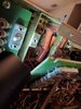
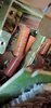
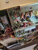
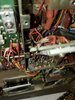
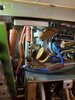
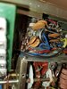
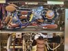
Thank you very much. I should know by tomorrow evening if it is relay related. That's when the replacement arrives. Is the shunt resistor you're talking about visible in any of these pictures?Does to me, too. Those capacitors don't have a lot to do with the idle-current bias setting. They serve as a path for the drive signal from the driver tube to the grids of the finals.
Lack of idle-current reading may be because the tubes are not turning on properly.
Could be because the meter is failing to show the current through the tubes.
The relay can cause either of those faults.
Or both.
Voltage reading across the shunt resistor is the only way to confirm which actual fault you're seeing. If the tubes draw current you'll see a DC voltage drop across it when you key it.
73
Attachments
-
 Screenshot_20210718-193140_Gallery.jpg1.4 MB · Views: 603
 -
 Screenshot_20210718-192834_Gallery.jpg952.9 KB · Views: 553
 -
 Screenshot_20210718-192822_Gallery.jpg983.3 KB · Views: 641
 -
 Screenshot_20210718-192811_Gallery.jpg989.9 KB · Views: 735
 -
 20210718_192650.jpg1.7 MB · Views: 734
 -
 20210718_192611.jpg1.5 MB · Views: 881
Between the two final sockets is a white ceramic cylinder, with a lead wire wrapped around each end and cloth-covered wire wound around the body. This is the shunt resistor. One end is grounded. The end connected to both tube sockets is your test point.
73
73
Found it. So if I understand correctly, if there is a meter related issue I should see a drop in DC voltage at the resistor once keyed. If the problem is relay related there should be no change since the relay isn't functioning? I'm also assuming the tubes need to be in place for the test?
Attachments
You should see no voltage at all across the shunt resistor in receive mode. If you do, the final tubes are not completely cut off while receiving. Can wear them out prematurely.
Put it in SSB transmit mode. If you see a change in DC voltage while turning the bias-adjust pot, the meter circuit is the problem. Best to leave it turned down until you can read the tube current on the meter. Too much idle current overheats the final tubes.
If you see no voltage drop at all while turning the bias pot, this tells you the tubes are staying shut off in transmit mode. Just doesn't tell you why.
Might be a good time to track down a tube tester and see that the tubes are not flat as a pancake.
73
dxChat
- No one is chatting at the moment.