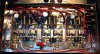
• You can now help support WorldwideDX when you shop on Amazon at no additional cost to you! Simply follow this Shop on Amazon link first and a portion of any purchase is sent to WorldwideDX to help with site costs.

IRF520A

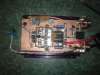
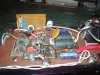
Pictures of Crusher`s work on the MOFSET project

73
Jeff
 

Attachments

  • MOSFET_AMP_001.jpg
    MOSFET_AMP_001.jpg
    312.9 KB · Views: 407
  • MOSFET_AMP_002.jpg
    MOSFET_AMP_002.jpg
    294 KB · Views: 411
I used the plastic screws, because the holes are to small for standard insulators. I need to install a relay/switch so that yes the bias will be turned off when in standby. First mosfet amp I ever built, so yeah I have a few items to address yet.
 
Last night, I installed a relay so that when keying circuit is activated, it turns on relay and supplies voltage to biasing circuit. That way there is only voltage applied when circuit is transmitting. Anymore ideas or suggestions are welcome.

Crusher
 
Last night, I installed a relay so that when keying circuit is activated, it turns on relay and supplies voltage to biasing circuit. That way there is only voltage applied when circuit is transmitting. Anymore ideas or suggestions are welcome.

Crusher
(y)(y)
 
Thanks 43, never really thought of installing it, did not seem like a problem at time but as i said, it was something i overlooked. That amp likes about a 2 watt DK and works nicely. Put about 12 hours on it now and seems to work fine. But I know what GRTS meant about nylon screws, as they heat up, plastic tends to expand and eventually pressure is taken off of transistor and can't dissipate heat nearly as well and poof. Magic smoke. LOL
 
Someone had told me at one point that IRF550A mosfets would make for a nice small amp. Boy were they wrong as so was I for not looking at datasheet. Just in case anyone else was thinking about trying something slightly bigger in the same family so to speak.
 
Thanks 43, never really thought of installing it, did not seem like a problem at time but as i said, it was something i overlooked. That amp likes about a 2 watt DK and works nicely. Put about 12 hours on it now and seems to work fine. But I know what GRTS meant about nylon screws, as they heat up, plastic tends to expand and eventually pressure is taken off of transistor and can't dissipate heat nearly as well and poof. Magic smoke. LOL

The issue with the screws can be solved by drilling the holes of the transistor tabs lager and using the teflon shoulder washers or by placing a flat metal strap across the transistors with a single screw through it to the heat sink.
 
GRTS, Galaxy has a model called 98VHP. It has 8 IRF520's as final section. Might want to take a look at that as well. Going to try a few other projects with IRF550's and IRF35X series. Anyone know how I can post a pic of this project?

Why use MosFets. When you could put in 4x2879's and get quite a few more watts out of it.


Owner of the World biggest Galaxy radio.
4X2879's 550-600watts. PEP.
 
Why use MosFets. When you could put in 4x2879's and get quite a few more watts out of it.


Owner of the World biggest Galaxy radio.
4X2879's 550-600watts. PEP.

LOL, if I want a big box I will build a big box for myself. But I have more fun just building and experimenting with the stuff. Trying new stuff out.
 
Last edited:

dxChat
Help Users
  • No one is chatting at the moment.
  • dxBot:
    Tucker442 has left the room.
  • @ BJ radionut:
    LIVE 10:00 AM EST :cool:
  • @ Charles Edwards:
    I'm looking for factory settings 1 through 59 for a AT 5555 n2 or AT500 M2 I only wrote down half the values feel like a idiot I need help will be appreciated