• You can now help support WorldwideDX when you shop on Amazon at no additional cost to you! Simply follow this Shop on Amazon link first and a portion of any purchase is sent to WorldwideDX to help with site costs.

Help with 858 Washington

Misfit

Member
May 1, 2017
19
8
13
53
Hello.
I could use some help with an 858 Washington.
Some history:
The radio was an eBay purchase. I received it in decent physical condition, but there were issues.
AM and SSB output was low, and a channel LED segment was getting flaky.
There were channel switches for upper and lower channels, but the regular 40 were gone. Seeing as it was beyond my knowledge, I took it to a local shop and he "undid" the extra channels and made it into a straight 40 channel radio again by undoing the jumps and cuts below the PLL.
When I got it back, the regular 40 were restored, but output was still low so I changed out the 2 x ECG236's (one driver, one final) for 2 x 2SC1969's. I also changed out VR15 and 16, VR7 and 8, C179, the AM regulator, the VCO (was an outhouse 458, put in a 945). I restored D23, and D47-(both were clipped).
D46 was intact.
I also found a youtube video wherein a guy with a similar issue changed out D53, so I did as well.
Nothing helps.
Output is still low; so low that AM audio is garbled and SSB is, well, a mess of squeals. I can ALMOST get some decent, halfway intelligible audio out of it, but it seems so touchy.
Driver 1969 is biased at 40 mA, final 1969 at 15 mA. (Thanks unit 399)
No matter how I try to align it, I can't get more than a couple watts out of it.
Looking at the bottom of the board, it appears that L37 was broadbanded, but....I do not recognize exactly how. The butchered job does not look anything like Secrect CB vol5, p 44...is it actually broadbanded? It looks like someone cut a trace above and then jumped it back to undo their mistake. It also looks halfway familiar to the method on Secret CB, but there is also a small ceramic capacitor (marked 82-pf?) jumping from one of L37's taps over toward FET6 I believe, which you can see here:

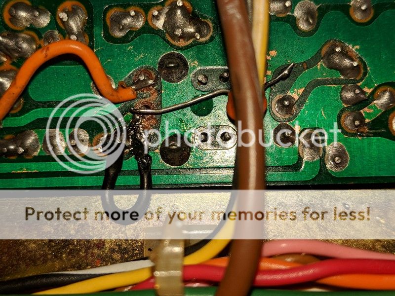
There is an electrical gap between the black jumper and the solder point of the cap...which looks like half of the broadband mod.....?
I am thinking that if I can "unbroadband" it, maybe I can recapture some wattage on 26.965-27.405. I would be happy to get this gem back to stock.

Can someone help me "unbroadband" this radio? (If it is actually).
If not, any help is appreciated.
 

http://unit399.wixsite.com/858ssb
Devour every word of it over the next few days. El Capo (Unit_399) will be along when he's able. If not I can struggle through. I won't say we are the best at the uPD858 here or even the most willing but we can help.
If after you have near memorized that page and your head hurts and your eyes are bleeding and you still want more, we have copies of the factory service manual. (several of us do) The factory service manual is excellent and detailed (the noise blanker section needs special attention) If you can obtain a PhotoFact so much the better (circuits are easier to trace).
Your first clue is the driver is a 2SC1306/2SC2166 the final is a 2SC1307/2SC1969/2SC2312sc bias is critical. BIAS IS CRITICAL. Did I say bias is critical ?
We'll move on past the basics when you're ready .
 
The driver was originally a 2SC1306. The same transistor used as the final in AM-only radios from the late 70s.

That part was replaced by the 2SC2166 in this type radio in the early 1980s.

Seems to me that the 2166 is a better driver than a 1969. Sure, the 1969 has a higher power rating, but it requires more drive power.

And there's not a lot of drive power available to the driver transistor in this radio.

If you can get your hands on a 2SC2166 to try, it should work better than the part that's in the driver circuit now. Won't know how much better until you try.

I know that using a 1969 as the drive stage in a 40-channel SSB radio works poorly in some other models, I never tried it in one of these. It crippled the 1980s-era radios we tried for this. Your radio is one generation older than those. Might respond differently, might not.

Could be this is the whole problem.

Or maybe just part of it.

One last thought. I'll assume you have peaked the tuning slugs in the transmit side already. Do any of the slugs appear to "peak" with the top of the slug dead-even with the rim of the hole in the top of the metal can?

If you see this, it's a sign that this can has a problem. The correct slug position for a proper peak is a turn or three or more below the rim. There is an internal capacitor that serves to tune these coils along with the inductance of the coil itself.

When this capacitor fails it will "push" the slug position needed to get a peak to a spot beyond its range of travel. But that "flush" position of the slug is in fact the slug's FUNCTIONAL end of travel. The coil's inductance will be maxed out with the slug set there. Looks like a "peak", since turning it counterclockwise any further drops the signal level the same as turning it clockwise back down into the hole would do.

A 'false peak'.

Anyway, a coil with a failed internal capacitor will also reduce transmit power in a big way. I need to post some pics of these tuneable coils with the slug at that "dead flush even" position.

Should call it "Beware the evils of the false peak!"

73
 
  • Like
Reactions: Cable Guy and NZ8N
Wow. Thanks so much for the replies.
Yes, I am indebted to unit 399 for his excellent site, and he was also kind enough to correspond directly with me as well.
(I just figured it wasn't fair to keep bugging him and updating him of all my stupid oversights and mistakes- ADHD tends to beat me up).
I do not have the factory service manual for this radio, but I have been referring to the TRC 449 manual.
I have a "genuine pulled 2SC2166" from a reputable eBayer ordered and on the way and I'll bias it to 40 mA.
I have 2.2uF 16v tantalums to replace C55, 68, 87, 179, 211 (which someone replaced with electrolytics).
I have a decent assortment of electrolytics to do most of the rest, but illI need to order the big ones.
In addition to 399's site I've been working off the TRC 449 schematic.
When I get the 2166 installed and biased I will update I guess.
As for the cans, L37 and L39 peak when the slugs are quite low, L30 and L32 peak close to the top...but the radio meter swings backward on AM. Though, my MFJ meter swings forward a bit on both AVG and peak settings when I back these down a tad.
There is an external disc cap on the underside of L37 (marked 82 see pic). I wonder if this was a hack to address the internal cap failing(?).
My goal is just to get this radio 12 Watts PEP SSB and 4x 2 Watt AM deadkey, or 8 Watts AM PEP.
If I can get there, I would ultimately like to do the 520 mosfet conversion as outlined by exit13, sand and paint a few spots in my buddy's auto body shop and then put it prominently in line as my special prized conversation piece radio.
 
Oh and quick question-
On the screws that hold the driver and finals to the chassis are 2 ring connectors with what appear to be tiny diodes epoxied into them and attached with yellow wires to the board.
One of them (on driver) actually popped out and I put it back by gently crimping it but if the wind blows it might pop out again.
What are these things?
 
It does help control issues that occur in the final section by swamping some of the bias voltage from the base of the bias voltage regulator to ground, as the finals get warm the diodes conduct more to ground and this lowers the bias voltage and helps by lowering the output of the final. I have seen these disabled and can only surmise that whoever did it was trying to keep the output from going down after the finals got a little too hot and the finals usually got a little too hot after they were hot-wired or bypassing regulators designed to keep the finals from overheating, But there you go I have seen literally hundreds of these come in with these diodes disabled.

bias diode.JPG
 
  • Like
Reactions: Cable Guy
Your MOSFET conversion would also require a larger power supply. The AM modulator is the rare and expensive uPC1156 chip. The added load that a MOSFET final will place onto the modulator may prove a bad idea.

Won't improve the performance all that much, even with the bigger power supply.

Unit 399's site shows a variable-carrier setup that will typically show 25-plus Watts of peak AM power with the stock final. The MOSFET won't do much more than that.

If that's the result you're seeking, skip the MOSFET.

73
 
Thanks for the insight Nomad, kopsicle and oldtech.
I wonder if gluing the diode would be advisable.
The existing epoxy is molded to the shape of the crimp collar of the ring connector but has lost its adhesion.

Nomad, I am sure you are correct. For now I will concentrate on getting it stock, as close to or better than factory spec as I can get.
I will re-cap it, replace the driver with the 2166 and try again.
If L37 has failed, I'm not sure where to go from there but perhaps I can pick the brains of you fine gentleman.
The pic I took of the underside of L37 makes me uneasy..
 
Last edited:
Well, after re-capping all the electrolytics and cleaning up the underside of L37, the performance is much better. With the 2166 and 1969, wattage is better too; 2watt deadkey on AM swings to about 8 PEP with speech, 5 watts avg. AM audio is that punchy, crisp 858 circuit-clipped, raspy squarewave that everyone tries to copy by removing limiters on Cobra 29s! The 858 provides that clarity and clean audio with the limiter intact.
SSB shows just about 12 Watts PEP.
Tuning L39 and the carrier balance has cleared up SSB.
Biasing the 2166 went well; 40 mA exactly.
The 1969, however, seems impossible to get into what should be normal territory.
Amperage shows between 90 and 170 mA...and then my Klein meter flakes out and just reads "LEAD".
Oddly, it does not get hot and I can talk on it fine.
The board has had the lowered power potential mod, but I notice there is no R204, nor are there diodes on the solder side of the board that unit 399 mentions on his site. R219 (47 ohm) is present on the solder side of the board.
Should I try and install R204? I do not see any mention of the diode part numbers...could these 3 missing parts cause my difficulty biasing the final?
I did consider installing an IRF 520, but keep the low power bulletin mod.
I wonder if doing so will "cure my biasing headache by cutting off the head"...?
 
the VR that controls the biasing may be bad. I have 3 of these radios and all had to have the VR's changed. would not adjust properly.
 
I actually did replace VR16 (as well as VR1,2,12,15,8 and one or two others)
VR16 is now a 500 ohm. I suppose I could have replaced a bad pot with another bad pot. These things are a bit flimsy sometimes..
 
A 'false peak'.

Anyway, a coil with a failed internal capacitor will also reduce transmit power in a big way. I need to post some pics of these tuneable coils with the slug at that "dead flush even" position.

Should call it "Beware the evils of the false peak!"

Meant to ask you about that. Does this internal cap go short or open? If open; can one bodge in a replacement cap? If so; what would that value be?

Of course, you can see why I am asking, since it is easier to put in a cap than to attempt to replace a coil that doesn't exist anymore for the most part - unless one robs Peter to pay Paul - so to speak.

Thanks!
 

dxChat
Help Users
  • No one is chatting at the moment.
  • dxBot:
    Tucker442 has left the room.
  • @ BJ radionut:
    LIVE 10:00 AM EST :cool:
  • @ Charles Edwards:
    I'm looking for factory settings 1 through 59 for a AT 5555 n2 or AT500 M2 I only wrote down half the values feel like a idiot I need help will be appreciated