
What do the Antenna experts here think of this? I pulled it off another forum and thought to bring it here. I was able to understand this.
Imax 2000 Ground Plane Kit Reviewed
What difference does the ground plane kit make on the Imax 2000 antenna?
After dissecting the Antron 99 and Imax 2000 antennas and discussing the construction and theoretical performance for each, I still wondered what the fiberglass antennas would do on the antenna range. Add to this, the constantly asked question about whether or not the available ground plane kits (GPK) made any difference in the performance of these antennas, and my curiosity peaked.
Copper Electronics has begun to sell a special ground plane kit which easily mounts to the Imax antennas' new mounting plate scheme. The ground plane kit for the Imax 2000 is the model A65-00005 and sells for just over $30. The Imax GPK consists of a nicely chromed metal bracket and four 6-foot fiberglass radials (which strangely resemble the top sections of the A99 antennas). The Imax 2000 is a .64 wave antenna which theory tells us highly benefits from a counterpoise beneath the feedpoint and radiating element. Typically on 5/8 and .64 wave antennas (both are considered the same), the counterpoise (ground plane) is at a 90 degree angle from the radiator. With the Imax GPK, the radials are angled at nearly a 45 degree angle downward from the radiator. Although I did not test the Imax 2000 with the 45 degree and then a 90 degree counterpoise to compare them, the new Imax GPK with 45 degree tilt did produce nearly the same results as theory dictates a 90 degree counterpoise would, so I have temporarily concluded that the difference in effects would be minimal.
Getting the Imax 2000 out to the antenna test range near Sacramento, CA was much more difficult than expected due to the unusual rains and winds the area experienced in early April. Once the range dried out and some commercial work was completed, I assembled and tuned the Imax 2000 for 27.200 MHz. This was the center frequency used for all testing as performed here. Measurments were taken at 10 degree intervals which is common practice with low band antennas. Ground effects were minimized with software compensation. The raw data is below the diagrams and text relating to the plots.
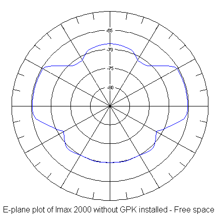
Imax 2000 in free space without GPK. To explain what it means to plot an antenna 'in free space', that means that the plot does not consider ground reflection, absorption, capacitance, refraction, etc. So if there were no Earth, as in free space, this is the radiated pattern of an Imax 2000. Viewing this plot chart, the tip of the antenna would be at the top of the chart, the feedpoint (and mounting point) is at the bottom. Each mark about the perimeter is 10 degrees. As you can see here, there is considerable radiation about the base of the antenna. In a situation where an Imax 2000 owner is susceptible to causing disturbance to consumer electronics by his transmissions, the Imax 2000 would blanket equipment located beneath its feedpoint with signal levels only slightly below the level on the horizon. Also note that the signal level at the horizon is the same as signal levels up to 30 degrees above the horizon. For sky-wave transmissions, this would be the ideal scenario. However, as we discuss below, ground effect distorts this pattern greatly which cancels out any benefits that would be achieved by a radiator with this pattern.
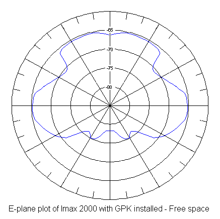
Imax 2000 in free space with GPK. Once the Imax GPK was added in our test, the pattern changed drastically. Besides a small amount of added efficiency, there are some other effects worth mentioning. First of all, notice that signal level on the horizon did not change. In free space, adding the Imax GPK to the Imax 2000 will not 'improve the range' of a system. The gain on the horizon is precisely the same with or without the Imax GPK installed. Second, and most worthy of note, the amount of radiation directly below and up to 45 degrees away from the area directly below the feedpoint experiences drastically reduced RF levels. In installations near consumer electronics (such as Imax 2000 with GPK installed in residential neighborhood), this could greatly reduce interference potential by an average of 10 dB. Second, note the reduced radiation in the area of 20 to 50 degrees above the horizon. Absent of ground effects, this would reduce sky-wave interference by as much as 10 dB. Since ground does effect the pattern greatly, this man-made interference reduction does not actually occur over real ground (as we will see below). However, there is still some benefit from this sky-wave reduction over ground, although at a higher angle than the free space values.
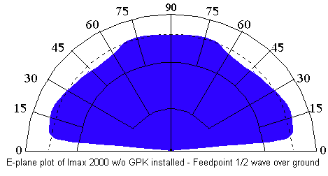
Imax 2000 without GPK installed with feedpoint mounted 1/2 wave over ground. Using software modeling and the free space information gathered from the range, we can determine what the actual radiation pattern would be over average ground. With the feedpoint located 1/2 wavelength over ground (18 feet in this case), the pattern varies from free space values drastically. Here, in this computer generated theoretical radiation pattern, you will notice the 'angle of radiation' (also called the 'take-off angle) is at approximately 7 degrees above the horizon. As you move further from the signal source, the signal would become weaker at ground level by an amount not proportional to the levels experienced above ground. The further you travel from the source, the higher you would have to be above ground for the signal levels to approach free space values. The Imax 2000 without the GPK has nearly an isotropic pattern when mounted 1/2 wave over average ground. As you increase the feedpoint mounting height over ground, the angle of radiation does decrease slightly. Until the feedpoint reaches over 1 wavelength above average ground, very little change was made. Heights considerably over 2 wavelengths above average ground (1 mile or more) bring the pattern slightly closer to free space values. However, since the FCC limits CB antenna height to 60 feet above ground (or 20 feet above mounting structure such as a building), I did not present that information here.
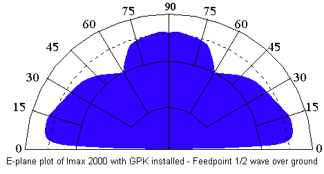
Imax 2000 with GPK installed with feedpoint mounted 1/2 wave over ground. When the Imax GPK was installed, the main lobe was directed more downward and less radiation about the base of the antenna was created. When modeled over average ground, these two things help to lower the 'angle of radiation' (take-off angle). Let's discuss this first. Since the angle of radiation is lowered, this means that as you travel further from the signal source, the received signal level will be slightly higher at a fixed far field distance from the source over the Imax 2000 without the GPK installed. Near field values are almost unchanged. What this means is that for communications close to the Imax 2000, there will be little (if any) noticed difference in signal strength to another station from the Imax 2000. However, far field transmissions would likely experience signals perhaps 2 dBm stronger from a GPK equipped Imax 2000. Once the receiving station is far enough away from the Imax 2000 signal source that curvature effect begins, the signal from a GPK equipped Imax 2000 over a non- GPK equipped Imax 2000 may have little more strength. Second point to consider in this over-ground plot is the reduced signal (and sensitivity) at angles of 60 degrees above horizon. Since most man-made interference received during the day is sky-wave, and usually high angle sky-wave, an Imax 2000 with the GPK installed will likely experience the 'noise floor' reduced by as much as 12 dB. This is quite significant if you are trying to carry on local communications when sky-wave noise is very high.
Conclusion: In both cases, it should be noted that the gain in the major lobe of the Imax 2000 was unchanged when the Imax GPK was added. Therefore, advertising claims of 'added gain' are arguably untrue. The net effect on the major lobe to sky-wave transmission and reception would be identical either way. However, sky-wave interference in the receiver would be reduced quite noticeably with the addition of the Imax GPK to the Imax 2000 while not affecting far field sky-wave performance at all. Also, since the angle of radiation is lowered when the Imax GPK is installed, Imax 2000 owners whose antennas are mounted less than 1 wavelegth above ground level should notice slightly greater useable ground wave range and a reduction in sky-wave interference during those communications. Both Imax 2000 owners with their antennas mounted either low or high above ground level should notice reduced 'TVI' and other non-intentional interference. For this reason alone, Imax 2000 owners would be advised to add the Imax GPK to their installation in either case.
Raw data:
Imax 2000 sweep
Degrees from
vertical Measured dBm
with GPK Measured dBm
without GPK
0 -67 -68
10 -66 -68
20 -66 -69
30 -66 -72
40 -70.5 -72
50 -70 -68
60 -68 -66
70 -67 -66
80 -66 -66
90 -66 -66
100 -66 -67
110 -67 -70
120 -68 -72
130 -72 -70
140 -82 -69
150 -75 -69
160 -76 -70
170 -73 -70
180 -73 -70
by Tech833
About the author:
The author is a professional broadcast engineer with over 20 years experience in the design, maintenance, and construction of broadcast transmitter and studio facilities. He has experience with high power antenna installations and has been involved with simple single antenna installations to complex phasing and directional arrays. The author is currently a successful contract engineer in California and has become highly respected and well known in the industry.
Imax 2000 Ground Plane Kit Reviewed
What difference does the ground plane kit make on the Imax 2000 antenna?
After dissecting the Antron 99 and Imax 2000 antennas and discussing the construction and theoretical performance for each, I still wondered what the fiberglass antennas would do on the antenna range. Add to this, the constantly asked question about whether or not the available ground plane kits (GPK) made any difference in the performance of these antennas, and my curiosity peaked.
Copper Electronics has begun to sell a special ground plane kit which easily mounts to the Imax antennas' new mounting plate scheme. The ground plane kit for the Imax 2000 is the model A65-00005 and sells for just over $30. The Imax GPK consists of a nicely chromed metal bracket and four 6-foot fiberglass radials (which strangely resemble the top sections of the A99 antennas). The Imax 2000 is a .64 wave antenna which theory tells us highly benefits from a counterpoise beneath the feedpoint and radiating element. Typically on 5/8 and .64 wave antennas (both are considered the same), the counterpoise (ground plane) is at a 90 degree angle from the radiator. With the Imax GPK, the radials are angled at nearly a 45 degree angle downward from the radiator. Although I did not test the Imax 2000 with the 45 degree and then a 90 degree counterpoise to compare them, the new Imax GPK with 45 degree tilt did produce nearly the same results as theory dictates a 90 degree counterpoise would, so I have temporarily concluded that the difference in effects would be minimal.
Getting the Imax 2000 out to the antenna test range near Sacramento, CA was much more difficult than expected due to the unusual rains and winds the area experienced in early April. Once the range dried out and some commercial work was completed, I assembled and tuned the Imax 2000 for 27.200 MHz. This was the center frequency used for all testing as performed here. Measurments were taken at 10 degree intervals which is common practice with low band antennas. Ground effects were minimized with software compensation. The raw data is below the diagrams and text relating to the plots.
Imax 2000 in free space without GPK. To explain what it means to plot an antenna 'in free space', that means that the plot does not consider ground reflection, absorption, capacitance, refraction, etc. So if there were no Earth, as in free space, this is the radiated pattern of an Imax 2000. Viewing this plot chart, the tip of the antenna would be at the top of the chart, the feedpoint (and mounting point) is at the bottom. Each mark about the perimeter is 10 degrees. As you can see here, there is considerable radiation about the base of the antenna. In a situation where an Imax 2000 owner is susceptible to causing disturbance to consumer electronics by his transmissions, the Imax 2000 would blanket equipment located beneath its feedpoint with signal levels only slightly below the level on the horizon. Also note that the signal level at the horizon is the same as signal levels up to 30 degrees above the horizon. For sky-wave transmissions, this would be the ideal scenario. However, as we discuss below, ground effect distorts this pattern greatly which cancels out any benefits that would be achieved by a radiator with this pattern.
Imax 2000 in free space with GPK. Once the Imax GPK was added in our test, the pattern changed drastically. Besides a small amount of added efficiency, there are some other effects worth mentioning. First of all, notice that signal level on the horizon did not change. In free space, adding the Imax GPK to the Imax 2000 will not 'improve the range' of a system. The gain on the horizon is precisely the same with or without the Imax GPK installed. Second, and most worthy of note, the amount of radiation directly below and up to 45 degrees away from the area directly below the feedpoint experiences drastically reduced RF levels. In installations near consumer electronics (such as Imax 2000 with GPK installed in residential neighborhood), this could greatly reduce interference potential by an average of 10 dB. Second, note the reduced radiation in the area of 20 to 50 degrees above the horizon. Absent of ground effects, this would reduce sky-wave interference by as much as 10 dB. Since ground does effect the pattern greatly, this man-made interference reduction does not actually occur over real ground (as we will see below). However, there is still some benefit from this sky-wave reduction over ground, although at a higher angle than the free space values.
Imax 2000 without GPK installed with feedpoint mounted 1/2 wave over ground. Using software modeling and the free space information gathered from the range, we can determine what the actual radiation pattern would be over average ground. With the feedpoint located 1/2 wavelength over ground (18 feet in this case), the pattern varies from free space values drastically. Here, in this computer generated theoretical radiation pattern, you will notice the 'angle of radiation' (also called the 'take-off angle) is at approximately 7 degrees above the horizon. As you move further from the signal source, the signal would become weaker at ground level by an amount not proportional to the levels experienced above ground. The further you travel from the source, the higher you would have to be above ground for the signal levels to approach free space values. The Imax 2000 without the GPK has nearly an isotropic pattern when mounted 1/2 wave over average ground. As you increase the feedpoint mounting height over ground, the angle of radiation does decrease slightly. Until the feedpoint reaches over 1 wavelength above average ground, very little change was made. Heights considerably over 2 wavelengths above average ground (1 mile or more) bring the pattern slightly closer to free space values. However, since the FCC limits CB antenna height to 60 feet above ground (or 20 feet above mounting structure such as a building), I did not present that information here.
Imax 2000 with GPK installed with feedpoint mounted 1/2 wave over ground. When the Imax GPK was installed, the main lobe was directed more downward and less radiation about the base of the antenna was created. When modeled over average ground, these two things help to lower the 'angle of radiation' (take-off angle). Let's discuss this first. Since the angle of radiation is lowered, this means that as you travel further from the signal source, the received signal level will be slightly higher at a fixed far field distance from the source over the Imax 2000 without the GPK installed. Near field values are almost unchanged. What this means is that for communications close to the Imax 2000, there will be little (if any) noticed difference in signal strength to another station from the Imax 2000. However, far field transmissions would likely experience signals perhaps 2 dBm stronger from a GPK equipped Imax 2000. Once the receiving station is far enough away from the Imax 2000 signal source that curvature effect begins, the signal from a GPK equipped Imax 2000 over a non- GPK equipped Imax 2000 may have little more strength. Second point to consider in this over-ground plot is the reduced signal (and sensitivity) at angles of 60 degrees above horizon. Since most man-made interference received during the day is sky-wave, and usually high angle sky-wave, an Imax 2000 with the GPK installed will likely experience the 'noise floor' reduced by as much as 12 dB. This is quite significant if you are trying to carry on local communications when sky-wave noise is very high.
Conclusion: In both cases, it should be noted that the gain in the major lobe of the Imax 2000 was unchanged when the Imax GPK was added. Therefore, advertising claims of 'added gain' are arguably untrue. The net effect on the major lobe to sky-wave transmission and reception would be identical either way. However, sky-wave interference in the receiver would be reduced quite noticeably with the addition of the Imax GPK to the Imax 2000 while not affecting far field sky-wave performance at all. Also, since the angle of radiation is lowered when the Imax GPK is installed, Imax 2000 owners whose antennas are mounted less than 1 wavelegth above ground level should notice slightly greater useable ground wave range and a reduction in sky-wave interference during those communications. Both Imax 2000 owners with their antennas mounted either low or high above ground level should notice reduced 'TVI' and other non-intentional interference. For this reason alone, Imax 2000 owners would be advised to add the Imax GPK to their installation in either case.
Raw data:
Imax 2000 sweep
Degrees from
vertical Measured dBm
with GPK Measured dBm
without GPK
0 -67 -68
10 -66 -68
20 -66 -69
30 -66 -72
40 -70.5 -72
50 -70 -68
60 -68 -66
70 -67 -66
80 -66 -66
90 -66 -66
100 -66 -67
110 -67 -70
120 -68 -72
130 -72 -70
140 -82 -69
150 -75 -69
160 -76 -70
170 -73 -70
180 -73 -70
by Tech833
About the author:
The author is a professional broadcast engineer with over 20 years experience in the design, maintenance, and construction of broadcast transmitter and studio facilities. He has experience with high power antenna installations and has been involved with simple single antenna installations to complex phasing and directional arrays. The author is currently a successful contract engineer in California and has become highly respected and well known in the industry.

