• You can now help support WorldwideDX when you shop on Amazon at no additional cost to you! Simply follow this Shop on Amazon link first and a portion of any purchase is sent to WorldwideDX to help with site costs.

Ever wonder what's inside those W2DU baluns?

Captain Kilowatt

Professional Amateur
Staff member
Apr 6, 2005
17,249
12,092
823
60
Nova Scotia,Canada
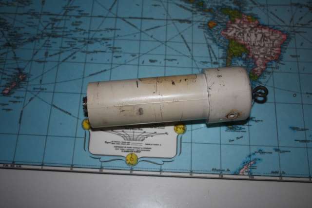
Wonder no more. I had a 1:1 W2DU "beam balun" on my tribander that I just finished taking down the other day. The connection points were looking bad so I decided that since I was rebuilding the antenna to last another year why not do everything including the balun.I bought this balun probably about 18 years ago or so and have heard that some companies are cutting short making them and using ferrite beads inside that are less than ideal. I have also heard that some of these W2DU baluns use a ferrite core which is OK but prone to overload with high power. Being the curious person I am (OK nosey then) I took mine apart to see what it was made of. Much to my surprise and delight I found that I had one of the very good original W2DU baluns as originally designed by Walter Maxwell himself,W2DU.It is not a cheap knock-off that is fairley common these days. It is a 1:1 air core balun wound with 14 gauge wire for high power handling without saturation of the core as will happen with a ferrite core. The first picture is of the unopened balun minus the attachment points to the antenna.You can see where the antenna connection points are on the side. The connection on the top is simply to hang the balun from something and is not connected to anything inside. I should note that this balun is used on a balanced antenna like a dipole or on some antennas that have a balanced feed like my A3 tribander that has a split driven element.


img1674ov.jpg


The second picture is of the insides of the 1:1 balun. Nicely made and still looking good after almost 20 years outdoors. The coax connects to the left side and the balanced output goes to the connections on the right.


edit_preview.php

img1675sn.jpg


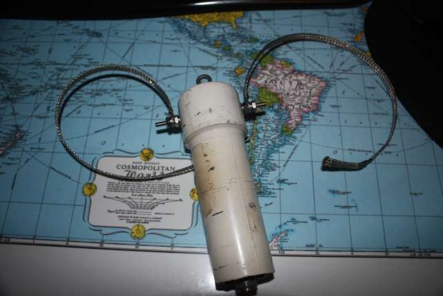
Lastly is the rebuild balun with new stainless hardware and tinned copper braid ready for attachment to the antenna. I left the leads long and will trim to length when the antenna is put up. I will install another set of ring terminals and use stainless hardware to attach it to the driver element.


img1679s.jpg
 
Last edited:

Bringing this up from the deep thanks to Google. :whistle:

CK, the second picture is apparently no longer available as it comes up with the image not found icon. Do you still have it?
 
Bringing this up from the deep thanks to Google. :whistle:

CK, the second picture is apparently no longer available as it comes up with the image not found icon. Do you still have it?


OK I had to do some digging but I found it. This is the insides of the W2DU "BEAM BALUN" I bought MANY years ago. It was used on my tribander and worked great. Apparently the design is different as it is an air-core balun so it is not prone to saturating at high power like a ferrite core balun is and it is not simply a choke but rather a TRUE balun. Unbalanced input on the left and balanced connections to the antenna on the right. I edited the old post above to show it there as well.

img1675sn.jpg
 
So if I'm doing this right, I count 24 _turns, which that is 8 winds of 3 wires into coils - but where are or where is - the WYE that ties this together - origin?
 
Thanks! So the interconnections, are not based necessarily on a WYE configuration, nor of a Trifilar re not a top to bottom, bottom to top - top to bottom - your 3-winds.

So the Capital letters of the above, signify the Top of the winds - presuming closer to the photos reconstruction - they are at the Balanced Lead end - where the ring lugs are - that is the TOP of the winds. A B and C.

The Bottom - is on the SO-239 end - and a (Center) and c (Coax Shield) - and is considered "Unbalanced"

They're tied as a series, not paralleled (Their winds are) - The Unbalanced is ACROSS the bottom winds - a to c - while C and a - are the balanced end - gotcha!

Thx!
(Why would they want to make this harder than it is? Referring to the "copycatters".)

Nicely done BTW - thanks a bunch - and the "Navigation Map" makes a good background for this project.

:+> Andy <+:
 
Thanks for the pic!

Hmmm, if it is a "W2DU" balun, I would have expected a string of ferrite beads over Teflon coax as that is the only configuration Walt ever really promoted that I'm aware of. Unadilla also sells "W2AU" baluns that IIRC are the conventional transformer type of blauns.

From what I've seen, "W2DU" baluns encased in PVC are characterized by being much longer than their transformer counterparts.

I have a Van Gordon balun that is on the 40/80 fan dipole we use for Field Day that is of the transformer type that works well.

I just received three of the W2DU balun kits from the Wireman that include fifty #73 beads, a 16" length of RG-303 cable, and a copy of the March 1983 article by Walt describing the choke balun.
 
Looks like a Ruthroff balun to me, and that is definitely a voltage balun for those who care. That being said, that is the first air core Ruthroff balun I recall seeing as people typically use ferrite cores for these baluns.

For his W2DU "baluns", Maxwell specifically used ferrite beads over RG-303 coax, although you can get the same effect with putting ferrite beads on other types of coax as well.


The DB
 
RG-142 many be a tight fit with only 0.002" clearance between the spec of the outer jacket and the ID of the mix 73 beads. I suspect that is why Walt chose RG-303 along with it being PTFE and able to handle nominal power ratings. IIRC, at the time he wrote the article, Part 97 limited amateurs to 1000 Watts DC input that was later modified to 1500 Watts PEP output.

For a real high power choke balun, RG-393 may be an interesting choice. Back in the '90s when I lived in Enid, OK one of the members had a 1000 foot reel of '393 gotten through MARS. We didn't really know what we had! I still have some short lengths of it but wish I'd have snagged about 100 feet of the stuff before I left.
 

dxChat
Help Users
  • No one is chatting at the moment.
  • dxBot:
    Tucker442 has left the room.
  • @ BJ radionut:
    LIVE 10:00 AM EST :cool:
  • @ Charles Edwards:
    I'm looking for factory settings 1 through 59 for a AT 5555 n2 or AT500 M2 I only wrote down half the values feel like a idiot I need help will be appreciated