I am looking to buy a Uniden Grant AM, upper side band, lower sideband mode switch if you have one get back to me please

You are using an out of date browser. It may not display this or other websites correctly.
You should upgrade or use an alternative browser.
You should upgrade or use an alternative browser.
-
You can now help support WorldwideDX when you shop on Amazon at no additional cost to you! Simply follow this Shop on Amazon link first and a portion of any purchase is sent to WorldwideDX to help with site costs.
-
The Father's Day Retevis RA89R Winner is Announced! Click Here for more info!
Wanted to buy Uniden Grant XL mode Switch
- Thread starter Low_Boy
- Start date

They sell both a single-deck 4-pole, 3-position switch and a two-deck version with 8 poles.
The 148 might get away with the single-deck one with 4 circuits. But a Cobra 2000 needs more than that.
Could be the simpler one will work. Just be sure to copy any pics on the sale listing that show the internal hookup to the pin numbers. Won't always be numbered the same as the original switch.
That is, if the original switch has any numbers on the lugs.
73
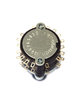

Whoa! Forgot the mode switch in that model is on a pc board.
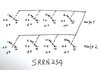
First need to identify the 'common' pin for each of the original four circuits on the original switch. Those will translate to pins 4, 9, 13 and 18 on the new one.
Identifying which pin is USB, AM and LSB on each of the four circuits would be next. The wires would have to be cut from the pcb-transition connector, stripped and soldered to the lugs on the new switch.
Naturally testing for continuity to do this may not work if the switch is bad. If it has one good section, the pattern for which pin is which mode should hold for the other three sections, though.
Not quite a chinese puzzle, but close enough.
At least the old one is arranged as four sets of four pins.
73
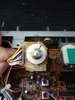
It would be a stab in the dark, but I would remove the switch from the board and pray the terminals were numbered. If that didn't work it would be time to reverse engineer the whole thing.
Don't count on the numbering being any help. Numbers on the old switch may or may not correspond to the numbers on the new one.
73
73
dxChat
- No one is chatting at the moment.
-
-
-
dxBot:boog351 has left the room.
-
@ BJ radionut:
June VHF
The American Radio Relay League (ARRL) is the national association for amateur radio, connecting hams around the U.S. with news, information and resources.www.arrl.org
-