• You can now help support WorldwideDX when you shop on Amazon at no additional cost to you! Simply follow this Shop on Amazon link first and a portion of any purchase is sent to WorldwideDX to help with site costs.

DX400 Bi-Lateral Issues

skiman1

Member
Aug 28, 2014
57
25
18
33
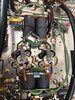
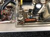
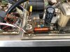
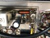
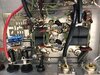
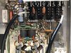
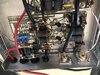
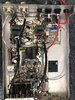
Hey Gang, Just picked up an DX400 off eBay, its an old Bi-Lateral with 4 - SRF2072 trannies and has 3 symptoms.

The good, the power output seems fine, driving it with 1.5w's with AM button in out's 100w carrier and 400'ish with swing, just like it should. That's where the good ends.

- When amp is on and tx'ign its normal power, the SWR is off the charts, like a 5, other amps I throw in line are fine, 1.2 - 1.5. I have the meter immediately following the amp, then into a Bencher LP filter. Meter is an MFJ-870, never any issues with the meter.

- The preamp is not working, just goes deaf, doesn't affect the Xmit power.

- When the SSB/delay button is pushed, its as if the output transistors/amp are taken out of line and I get stock power. When tx'ing no delay can be heard kicking the relay in and out, again like the amp is off.

Honestly I could care less about the Preamp working, I've never used them anyway on every amp I've ever had, but obviously all the either issues are the real issues, but sure its connected.

I'm sure just a couple of simple components, but not a super troubleshooter kinda guy. Any help would be welcome, thanks in advance!
 

SRF2072, the high-gain version of the MRF455, if memory serves. Prone to be unstable and oscillate. Amplifier builders liked the high wattmeter readings this would deliver, along with a 'soup' of other unwanted frequencies.

Don't remember seeing this amplifier, but I'll guess that it lacks negative feedback on the transistors.

Negative feedback generally does two things. Reduces the harmonic and spurious-frequency output from the transistors, and lowers the input impedance.

Some pics with decent focus and lighting could be helpful.

Best fix for the preamp is to jump around it, take it out of the circuit.

If you're REALLY lucky, the preamp relay will have a clear-plastic top cover that can be snapped off the relay. Then remove the moving contacts and armature.

A single strand from a piece of stranded hookup wire works best for this.

smzugY.jpg


This will bypass it completely and prevent problems with the "standby side" circuit that passes through the preamp relay.

Easier than removing the circuit board to do this.

73


See gut shots below, I don't even see that second relay, perhaps already modded?
 

Attachments

  • IMG_0859.jpg
    IMG_0859.jpg
    2.3 MB · Views: 172
  • IMG_0857.jpg
    IMG_0857.jpg
    2.6 MB · Views: 207
  • IMG_0856.jpg
    IMG_0856.jpg
    2.3 MB · Views: 166
  • IMG_0855.jpg
    IMG_0855.jpg
    2.1 MB · Views: 163
  • IMG_0854.jpg
    IMG_0854.jpg
    1.6 MB · Views: 179
  • IMG_0853.jpg
    IMG_0853.jpg
    1.8 MB · Views: 171
  • IMG_0852.jpg
    IMG_0852.jpg
    1.8 MB · Views: 167
  • IMG_0851.jpg
    IMG_0851.jpg
    1.7 MB · Views: 195
  • IMG_0850.jpg
    IMG_0850.jpg
    3.1 MB · Views: 226
Shoulda said "Texas Star", and I would have put my foot back on the floor before it could reach my mouth.

The SSB switch on this model does two things. First, puts a capacitor onto the relay to keep it from chattering. Second, it cuts the drive level about in half, more or less.

That's the only way to make this kind of amplifier sound right on sideband. You can drive it almost twice as hard on AM before the audio quality will suffer. The attenuator side of the SSB switch is to hold down the drive level and improve the modulation quality.

(edit) Just re-read your original post. Did you mean that the relay does not key up at all with the SSB button pushed in? That can't be right, clearly.

73

I know its not right, its why I'm here ha ha! :)

With delay engaged, no relay click, no "amp" output, just stock power from the radio. like the amp is bypassed or off. Nothing in here smells burnt, all looks clean too
 
Last edited:
Looking at the schematic, the only explanation I can figure would be for C4 to fail as a short circuit. It's the 1000 uf cap that slows down the relay for SSB. If it's shorted, that should prevent it from keying.

And eventually blow up the keying transistor Q1.

73
 
  • Like
Reactions: skiman1
I also have a dx400 like this one... I have no output power and this is blown it's a 100ohm resistor... think it's a 1 watt not sure... also the mica cap.next to it says 330k I think... what are the values and where can I get these for replacement... also need the wrapped ferride
 

Attachments

  • Screenshot_20221015-231446_Chrome.jpg
    Screenshot_20221015-231446_Chrome.jpg
    1.2 MB · Views: 60
The 100 ohm and the toroid combiner coil both look perfectly okay. I have seen my share of the toroid combiner coil burned black. But this one looks new.

I think I hear wishful thinking, hoping the cheapest part you see will fix the trouble.

A linear amplifier with no output power is too much like "My car won't start". The list of possible causes is kinda long, but the symptom is short.

Troubleshooting is done by identifying what does work. This will lead you to what part of the thing has quit. Do you have a multimeter to make any electrical measurements?

Lately it seems we see more and more bad pushbutton switches. And that's a nightmare to fix.

Failed RF power transistors are a common failure. Trouble is they always look perfectly okay, blown or not. There is a 10 ohm resistor from the base terminal of each RF power transistor to ground. If any of those look scorched, you have at least one bad transistor. I would check there first.

73
No that was a pic of one not bad here's the pic of the one on mine
 

Attachments

  • 20221015_233241.jpg
    20221015_233241.jpg
    1.1 MB · Views: 54
  • 20221015_233247.jpg
    20221015_233247.jpg
    1.1 MB · Views: 49

dxChat
Help Users
  • No one is chatting at the moment.
  • @ Wildcat27:
    Hello I have a old school 2950 receives great on all modes and transmits great on AM but no transmit on SSB. Does anyone have any idea?
  • @ ButtFuzz:
    Good evening from Sunny Salem! What’s shaking?