
The old adage "You gets whats ya pays for" never seems to be wrong.
This project is barely begun. It should result in a drop-in replacement for the RCI2995DX "firestarter" amplifier board that uses four IRF520 switchmode MOSFETs as a 100-Watt linear amplifier.
The plan is to use a single 50-Volt RF-rated MOSFET made by NXP called the "MRF101".
But the eval kit for that part still has not arrived.
What did arrive today are a couple of candidate voltage step-up inverters I'll need to get 50 Volts DC in a 13.8-Volt base radio.
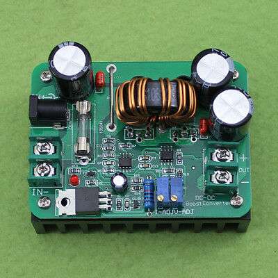
Here's the pic for a 600-Watt step-up inverter from the Chinabay listing.
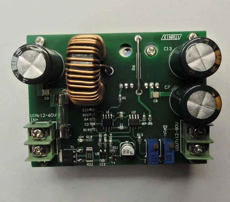
And here's what they sent.
If I wanted to be a jerk, I could probably get it free by invoking Fleabay's "As Pictured" rule. But I was pretty sure I would need to hack this thing anyway, so I really don't care.
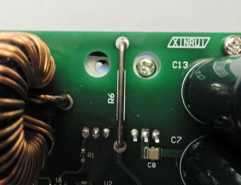
The sharp-eyed reader may spot a small assembly crock in the one they sent me.
Like this:
Looks like this from the side.
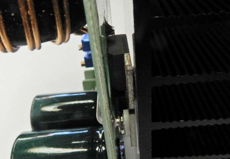
Sure enough, the Sil-pad stays where it was when the pcb is unbolted from the heat sink.
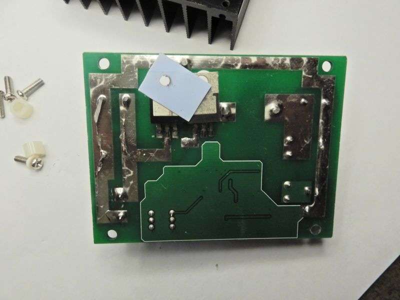
A good thing I didn't plan to just hook it up and try with a dummy load right away.
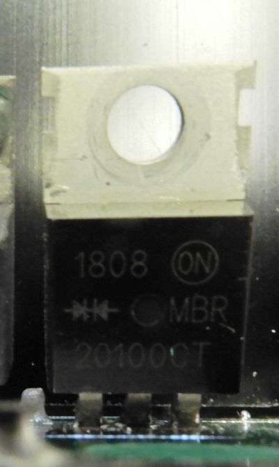
The part that was bolted down is a full-wave rectifier, containing two diodes.
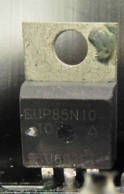
The one that wasn't bolted down is the switchmode MOSFET.
Seems like a bad idea. Fortunately I have the hardware to finish building this unit before I power it up.
I did not get a good pic of the markings on the two tiny surface-mount integrated circuits. But for those playing along at home, the controller chip is type UC3843 current-mode PWM controller made by ST Micro.
Found it at alldatasheet.com.
The other chip is a generic LM358 dual opamp.
First task, if it survives a dummy-load test, is to devise a shutdown input. I don't want this thing running while the radio is receiving. A switchmode supply on an open unshielded board like this tends to radiate a lot of unwanted RF. If it only runs while the mike is keyed, this won't matter a lot. But this chip doesn't sport that feature. Gotta be a way to implement a shutdown input, though. Might last longer if the linear's power is only applied after the relay has time to change from receive to transmit.
The listing describes this toy as a 600-Watt step-up inverter. With any luck it's big enough to run a single 100-Watt RF power transistor and be comfortable.
Oh, and before you ask, we're doing the final test on a batch of three dozen Peel-'N-Stick variable modules. They should be packed up and ready to ship this week. Won't sell them without first doing a functional test.
73
This project is barely begun. It should result in a drop-in replacement for the RCI2995DX "firestarter" amplifier board that uses four IRF520 switchmode MOSFETs as a 100-Watt linear amplifier.
The plan is to use a single 50-Volt RF-rated MOSFET made by NXP called the "MRF101".
But the eval kit for that part still has not arrived.
What did arrive today are a couple of candidate voltage step-up inverters I'll need to get 50 Volts DC in a 13.8-Volt base radio.
Here's the pic for a 600-Watt step-up inverter from the Chinabay listing.
And here's what they sent.
If I wanted to be a jerk, I could probably get it free by invoking Fleabay's "As Pictured" rule. But I was pretty sure I would need to hack this thing anyway, so I really don't care.
The sharp-eyed reader may spot a small assembly crock in the one they sent me.
Like this:
Looks like this from the side.
Sure enough, the Sil-pad stays where it was when the pcb is unbolted from the heat sink.
A good thing I didn't plan to just hook it up and try with a dummy load right away.
The part that was bolted down is a full-wave rectifier, containing two diodes.
The one that wasn't bolted down is the switchmode MOSFET.
Seems like a bad idea. Fortunately I have the hardware to finish building this unit before I power it up.
I did not get a good pic of the markings on the two tiny surface-mount integrated circuits. But for those playing along at home, the controller chip is type UC3843 current-mode PWM controller made by ST Micro.
Found it at alldatasheet.com.
The other chip is a generic LM358 dual opamp.
First task, if it survives a dummy-load test, is to devise a shutdown input. I don't want this thing running while the radio is receiving. A switchmode supply on an open unshielded board like this tends to radiate a lot of unwanted RF. If it only runs while the mike is keyed, this won't matter a lot. But this chip doesn't sport that feature. Gotta be a way to implement a shutdown input, though. Might last longer if the linear's power is only applied after the relay has time to change from receive to transmit.
The listing describes this toy as a 600-Watt step-up inverter. With any luck it's big enough to run a single 100-Watt RF power transistor and be comfortable.
Oh, and before you ask, we're doing the final test on a batch of three dozen Peel-'N-Stick variable modules. They should be packed up and ready to ship this week. Won't sell them without first doing a functional test.
73
Last edited:

