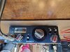
I picked up this cb used with no mic. I was able to determine that it was wired for a Midland and everything worked except for there was no modulation. It would receive and transmit a carrier (confirmed with a local 7 miles away) but there was no modulation. Upon advice from this same local it was advised that on older radios a cap, as opposed to an audio chip, was responsible for modulation and that I should recap the radio. I did just that and now there is no rx or TX. I confirmed the right caps, right values and right orientation. What I didn't check before install was that the new caps were indeed good ( brand new). I've considered putting the old caps back but before I do I was hoping for some help. Any and all advice is welcome. A schematic would also be great! Thank you in advance!

You are using an out of date browser. It may not display this or other websites correctly.
You should upgrade or use an alternative browser.
You should upgrade or use an alternative browser.
-
You can now help support WorldwideDX when you shop on Amazon at no additional cost to you! Simply follow this Shop on Amazon link first and a portion of any purchase is sent to WorldwideDX to help with site costs.
-
A Winner has been chosen for the 2026 July 4th Retevis RA89R Giveaway! Click Here to see who won!
Smokey 23 channel troubleshooting no tx/rx
- Thread starter Champo
- Start date
A bad cap is possible, but least likely.
Check for solder bridges and loose connections on all the caps that you replaced.
In the future, don’t replace all the caps at once. Only replace a few at a time, then keep checking the radio periodically.
Clean the channel selector plus all switches.
I also suspect the mic you’re using still might not be wired totally correct for that radio. With everything else working except modulation, that eliminates most of the radio, particularly the push pull audio transistors in the back. If you can get it back to the way it was, check the PA function.
The name on that radio was suitable during the time period it was sold. A real collectors item and worth restoring IMO, especially one in such great cosmetic condition. Lets hope you get that one working.
A bad cap is possible, but least likely.
Check for solder bridges and loose connections on all the caps that you replaced.
In the future, don’t replace all the caps at once. Only replace a few at a time, then keep checking the radio periodically.
Clean the channel selector plus all switches.
I also suspect the mic you’re using still might not be wired totally correct for that radio. With everything else working except modulation, that eliminates most of the radio, particularly the push pull audio transistors in the back. If you can get it back to the way it was, check the PA function.
The name on that radio was suitable during the time period it was sold. A real collectors item and worth restoring IMO, especially one in such great cosmetic condition. Lets hope you get that one working.
I appreciate the reply and the advice. All of the caps that were removed have also tested OK so I'll remove the new ones and reinstall the old ones. What would you recommend for a mic solution. I can post pics of the mic connections on the inside of the case if necessary. I forgot to mention in my original post that there was a blown ceramic cap near the board ground screw. I replaced that prior to the recapped when everything was working minus the modulation.
I personally like the old coffin style mics, but for testing, any 500 ohm dynamic mic will work.
By looking at the back side of the connector look for the shield or ground pin. It will either be pin 1 or 2. That pin will have a wire connecting to circuit board ground. As shown the ground pin is 1 on the Cobra and pin 2 on the Midland. All other pins will follow in accordance. Unless you know the mic you have is working on another radio, I would remove the cover and test the cartridge. Follow the wires from the cartridge to the key. Those two wires should read about 500 ohms across them. Also check for continuity on all key’s contacts. Cleaning and lubing mic keys is discussed elsewhere.
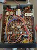
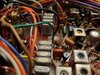
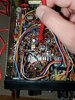
Meanwhile I’m checking for a schematic for that radio. By looking at your inside photo, many old 23 channel radios use the push pull audio transistors like yours. At least that’s a clue to a board that’s possibly used on another brand. The 10.180 mixer crystal I spotted also narrows the search down.

By looking at the back side of the connector look for the shield or ground pin. It will either be pin 1 or 2. That pin will have a wire connecting to circuit board ground. As shown the ground pin is 1 on the Cobra and pin 2 on the Midland. All other pins will follow in accordance. Unless you know the mic you have is working on another radio, I would remove the cover and test the cartridge. Follow the wires from the cartridge to the key. Those two wires should read about 500 ohms across them. Also check for continuity on all key’s contacts. Cleaning and lubing mic keys is discussed elsewhere.
Meanwhile I’m checking for a schematic for that radio. By looking at your inside photo, many old 23 channel radios use the push pull audio transistors like yours. At least that’s a clue to a board that’s possibly used on another brand. The 10.180 mixer crystal I spotted also narrows the search down.

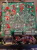
You've been a huge help and I'm extremely grateful for your time. It definitely isn't wired for a cobra because back when it was working but not modulating I tried a cobra mic ( cobra 73 and astatic d104m6b) but there was no receive. I had a workman C4P4M adapter (cobra to midland) and that brought in the receive audio and transmitted a carrier but no modulation. I then rewired the cobra 73 in several different configurations in an attempt to get it to modulate without any success. The cobra 73 was functional prior to rewiring but I do not have a midland radio to confirm its functionality since I rewired it. The Astatic is functional and works on my Uniden and Yaesu with Cobra adapter. Here are some better pictures of the mic plug and crystals as well. I have 6 of the 21 original caps back in and I'm hoping to get the rest in tonight. If not I'll have to pick it up tomorrow.I personally like the old coffin style mics, but for testing, any 500 ohm dynamic mic will work.
By looking at the back side of the connector look for the shield or ground pin. It will either be pin 1 or 2. That pin will have a wire connecting to circuit board ground. As shown the ground pin is 1 on the Cobra and pin 2 on the Midland. All other pins will follow in accordance. Unless you know the mic you have is working on another radio, I would remove the cover and test the cartridge. Follow the wires from the cartridge to the key. Those two wires should read about 500 ohms across them. Also check for continuity on all key’s contacts. Cleaning and lubing mic keys is discussed elsewhere.
Meanwhile I’m checking for a schematic for that radio. By looking at your inside photo, many old 23 channel radios use the push pull audio transistors like yours. At least that’s a clue to a board that’s possibly used on another brand. The 10.180 mixer crystal I spotted also narrows the search down.
View attachment 44498
Attachments
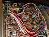
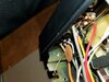
I forgot to mention that the white wire on the top right mic plug is tied into the gray wire below it.You've been a huge help and I'm extremely grateful for your time. It definitely isn't wired for a cobra because back when it was working but not modulating I tried a cobra mic ( cobra 73 and astatic d104m6b) but there was no receive. I had a workman C4P4M adapter (cobra to midland) and that brought in the receive audio and transmitted a carrier but no modulation. I then rewired the cobra 73 in several different configurations in an attempt to get it to modulate without any success. The cobra 73 was functional prior to rewiring but I do not have a midland radio to confirm its functionality since I rewired it. The Astatic is functional and works on my Uniden and Yaesu with Cobra adapter. Here are some better pictures of the mic plug and crystals as well. I have 6 of the 21 original caps back in and I'm hoping to get the rest in tonight. If not I'll have to pick it up tomorrow.
Attachments
I returned all of the original caps to their original locations but unfortunately it didn't change any thing. Regrettably I think I damaged something when I replaced them originally. The green meter light is illuminated and shuts off when you key the mic but it no longer transmits a carrier. Their is static that comes from the speaker however it is lower than it should be. If you touch certain spots on the board with the meter lead the sound will increase to a normal level. I forgot to check the pa and external speaker so I will do that tomorrow morning. There is also a click or pop in the speaker when the channel selector is rotated or the pa/cb switch is manipulated. If the mic is removed from the jack the reduced static disappears. I hope this helps in some way and I'm keeping my fingers crossed that a schematic is still available by some miracle. I truly appreciate your willingness to help me. Thank you! You're awesome!I forgot to mention that the white wire on the top right mic plug is tied into the gray wire below it.
I was able to confirm that PA is not operable. When you key up the low sounding hash from the speaker disappears but nothing from the PA. When a speaker is plugged into the external speaker jack a high pitched oscillating signal is heard like a motor boat.I returned all of the original caps to their original locations but unfortunately it didn't change any thing. Regrettably I think I damaged something when I replaced them originally. The green meter light is illuminated and shuts off when you key the mic but it no longer transmits a carrier. Their is static that comes from the speaker however it is lower than it should be. If you touch certain spots on the board with the meter lead the sound will increase to a normal level. I forgot to check the pa and external speaker so I will do that tomorrow morning. There is also a click or pop in the speaker when the channel selector is rotated or the pa/cb switch is manipulated. If the mic is removed from the jack the reduced static disappears. I hope this helps in some way and I'm keeping my fingers crossed that a schematic is still available by some miracle. I truly appreciate your willingness to help me. Thank you! You're awesome!
That’s Midland mic connections no doubt. The white wire is your audio and the short black wire going to the large gray cable (coax) is the common ground and shield.
What I did find so far is not a clone, but the board layout on the Pearce Simpson Bobcat 23C or 23E is similar.
http://www.cbtricks.com/radios/pearce_simpson/bobcat_23c/index.htm
I do know there was a schematic included in the original manual for that radio. Typically these old radios had a small schematic printed on the last page of their manuals. Whenever I have one of those manuals I always scan and enlarge it. Given enough time one will show up. The search for one becomes a little more difficult because most everything will point to the various "Smokey and the Bandit" radios as seen in the movies.
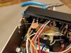
There is a ham radio website where a gentleman has the same radio and performed a 10 meter conversion on it. He said he had the original schematic and manual. I sent an email asking if I could get a copy so hopefully I'll get a reply. There is no date on the post though sobit could be from 10 years ago for all I know. I have a quick question on the transformer, or what I believe is a transformer, in the top center of the board. It has 6 legs; three on the right and three on the left. The three on the left all have 13.8vdc on them. On the right side, the two closest to the front have 13.8 vdc but the furthest pin has no voltage. Does voltage flow into or out of these pins? I also have 13.8 vdc at the locations marked in red.That’s Midland mic connections no doubt. The white wire is your audio and the short black wire going to the large gray cable (coax) is the common ground and shield.
What I did find so far is not a clone, but the board layout on the Pearce Simpson Bobcat 23C or 23E is similar.
http://www.cbtricks.com/radios/pearce_simpson/bobcat_23c/index.htm
I do know there was a schematic included in the original manual for that radio. Typically these old radios had a small schematic printed on the last page of their manuals. Whenever I have one of those manuals I always scan and enlarge it. Given enough time one will show up. The search for one becomes a little more difficult because most everything will point to the various "Smokey and the Bandit" radios as seen in the movies.
Attachments
If the meter lead is connected to this leg of the transistor the volume from the speaker comes back and you can squelch the volume. I don't know if that is helpful or not.There is a ham radio website where a gentleman has the same radio and performed a 10 meter conversion on it. He said he had the original schematic and manual. I sent an email asking if I could get a copy so hopefully I'll get a reply. There is no date on the post though sobit could be from 10 years ago for all I know. I have a quick question on the transformer, or what I believe is a transformer, in the top center of the board. It has 6 legs; three on the right and three on the left. The three on the left all have 13.8vdc on them. On the right side, the two closest to the front have 13.8 vdc but the furthest pin has no voltage. Does voltage flow into or out of these pins? I also have 13.8 vdc at the locations marked in red.
Attachments
One last question. Could these symptoms be the result of a bad transistor? They're cheap and I could swap them. I just don't want to throw parts at it if they are unlikely to be the cause. I did remove the transistor in question after the initial recap to test following a test procedure online however my test results did not match what the non results should have been. I was not convinced by the results though. I removed a second on that same trace with similar results. At this point I'm grasping at straws. Unfortunately I was unable to make heads or tails out of that schematic for the other radio in relation to the smokey. I screwed the pooch some how.If the meter lead is connected to this leg of the transistor the volume from the speaker comes back and you can squelch the volume. I don't know if that is helpful or not.
One final question Sunbulls if you'll entertain it. Back before everything else to the original issue of everything working except modulation. Since we can surmise based on you mic plug verification that the Midland adapter should have worked with that radio, what do you think the cause of the no modulation might have been? Perhaps I can approach all of this from a different direction.
I don’t know if you did this, but I once inadvertently caused additional damage when I forgot to tape over the bare speaker wire ends after disconnecting them. Those wires flailing around without any protection is a disaster waiting to happen.
To name just one, creating an open or shorted diode is another common cause for many mic related mishaps.
Look again at the Bobcat schematic that I believe is very similar. T10 is the audio output transformer in the middle for your board. Actually there are 3 leads on the input and 4 on the output. All three leads on the input should show 13.8 volts and two of output leads will also read 13.8 volts. The remaining two output leads connect to the internal or external speaker.
My mistake. You are correct. There are 4 on the right and the two closest to the front have 13.8vdc and the other two fo not.I don’t know if you did this, but I once inadvertently caused additional damage when I forgot to tape over the bare speaker wire ends after disconnecting them. Those wires flailing around without any protection is a disaster waiting to happen.
To name just one, creating an open or shorted diode is another common cause for many mic related mishaps.
Look again at the Bobcat schematic that I believe is very similar. T10 is the audio output transformer in the middle for your board. Actually there are 3 leads on the input and 4 on the output. All three leads on the input should show 13.8 volts and two of output leads will also read 13.8 volts. The remaining two output leads connect to the internal or external speaker.
View attachment 44517
dxChat
- No one is chatting at the moment.
-
-
-
@ BJ radionut:Scheduled for Jul 4, 2026 Saturday Live Streams:
To celebrate the 250th birthday of our great nation. We are giving away not just one, but multiple antennas! The Grand prize is the CaHR-Tenna Hydra Antenna, along with several other antenna prizes that will be announced throughout the giveaway. Whether you're a new ham, portable operator, POTA activator, or an experienced HF operator, this is your chance to upgrade your station. Prizes Include: HRA Hydra Antenna (Grand Prize) Additional antennas from HRA More prizes may be added during the giveaway! -
-
