• You can now help support WorldwideDX when you shop on Amazon at no additional cost to you! Simply follow this Shop on Amazon link first and a portion of any purchase is sent to WorldwideDX to help with site costs.

GALAXY SATURN NO RECIEVE

Heed my advice about CONVERSIONS, so yes, no 65.

Wiper has 8V - too much.

Should be adjustable - really shold not be higher than 7.2 V and goes as low as 0.1V (Foil Ground)

If Wiper doesn't change - your RFG pot is open - no connection to Foil Ground. You have to check it.

So review the work, SQ and RF Gain share common Ground Tie.

You need to Check RF Gain pot out of circuit to verify it's bad. Else if it's NOT bad, as in you have Variable between BOTH Constants One sides ohmic reading rises as the other side falls, as you turn the knob - if you can verify the Ohms and Wiper is working - you'll need to verify the Circuit.


  • I need to point out something here...
  • Locate your Head - should be LOCATE YOUR HEADER FOR THE POT - goes INTO the board...

shieesh...

If Squelch is adjustable, yet RF Gain is not, then Replace RF Gain pot.
I will do my checks and let u knkw so far the rf gain pot is reading good .. this a continuity test from. R66 ro rf gain that is fine....from the header to r 66 is fine
 
Last edited:
Is your RF Gain Pot voltage adjustable, that you can see the change at R66?

Both sides of R66.

Because when a pot output "pops up" to the supply rail voltage, tells me thru Ohms law, there's nothing on the line (no load) nothing to pull draw current that in turn lowers the measured voltage - so when you have the 8 volts on the WIPER arm, then that tells me, the line going to TR17 is high -impedance (high resistance) Or Open Line (O.L.)

Then somewhere in the mess of that 2SC2999 conversion is the fault.

To ADD:

When checking circuits doing a Continuity Check, you'll also need to verify the wiring.

So if you get 8 volts, means you have power...
You say the pot is variable, that's good news...
But, what about ground?
To prevent the parts in the circuit from being blown up from wrong voltages, the potentiometers own CONSTANT resistance is tied off to ground not just power, - ground too.

RF Gain and Squelch, because of what they do, ALL their terminals LEGS, Lugs - insert favorite connection point terminology here - are connected back inside the radio in one form or another - be it power, ground or working voltage for their loads.


So that means you have to locate #57 and VERIFY it's Foil Board Ground.​
 
Last edited:
Makes me think the ground wire on the RF Gain control has come loose, maybe at the far end away from the control. The center lug should read zero Volts when turned all the way to the right. If the center lug reads 8 Volts, this is why the receiver is deaf.

73
 
  • Like
Reactions: NZ8N
Makes me think the ground wire on the RF Gain control has come loose, maybe at the far end away from the control. The center lug should read zero Volts when turned all the way to the right. If the center lug reads 8 Volts, this is why the receiver is deaf.

Now I did a check j as u asked. When I got all to the right the center lug reads zero .when I t goes to the left is shows the 8volts .should the other lug show 8volts.? Regardless?

73
 
Ok, if the Pot can show varying voltage...

The Circuit works on the priciple of a waterfall, the pot controls how much water "falls" to ground.

The objective is to change the voltage difference between the Emitter (Towards L6) and Collector - (Towards L7)

Collector should always have 8 volts.

Base lead is designed as a "Common Base" amplifier - for Current - not voltage.

Emitter lets L6 call the shots - if there's too much voltage at the Emitter - the "product" (RF) of L6 is Drowned out by the DC "static" voltage - and there is not enough potential difference between Collector to Emitter to allow any current to flow.

Now, for the BASE - that is a different story.

8 Volts from the Collector will always flow into the Base - thru the PN junction it has with the Collector.

upload_2021-6-3_20-51-30.png

Take a look at the Maximum RATINGS the GALAXY
Service Manual sez...
upload_2021-6-3_20-53-59.png

Better check L6 - make sure it's not opened up...​

There's a LOT more to this but I'm trying to work in stages for you...

 
@BAGEBOY - Before I go any further, I want to point out something...

Look at this post in the 2SC2999 MOD analysis thread...
https://www.worldwidedx.com/threads/2sc2999-mod-analysis.161809/page-4#post-633475

There's something VERY important in that thread, that if you want some success in getting the radio to receive again, you may have a "bitter pill" to swallow.

Again, I speak from experience - and it's unfortunate that you want to learn this the hard way.

The above thread link "bashes" (to death) the subject, and it's rightfully so.

It should be left to serve as a warning to others that are going to try and put lipstick on a pig and call it something else.

Why? Reread the post, and look at those pretty pics and graphics I spent a lot of time on to help others avoid this moment.

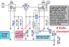
The 2SC2999 is set up as a VOLTAGE amplifier in nearly EVERY circuit it is used in - in almost every current Galaxy platform, the 2SC1674 is used as a Common Base (Current) Amplifier - in the 2SC2999 circuits - it's oriented to operate as a Common Emitter (Voltage) amplifier (Stryker).

The 2SC1674 is used as a CURRENT amplifier to not amplify the signal - it's to SELECT it from the mess L6 is delivering.

The 1674 is also used in Cobra 29's 25 and Uniden 66/68 and 76/78 series as well - but then again as a voltage amplifier PROPERLY designed for it.

L6 is a very broad banded coil - the RF amp design is to LIMIT signal strength to a window that allows L7 and L8 to work as a Band Pass Filter (or Pre-Selector) so the IF can mix with the RF present from L7 and L8 (greatly diminished) - send it thru a Crystal Filter and on the other end is hopefully the channel you wanted to hear.
  • Quadrature design coils, which L6 can be considered defined as, are crisscrossed winds (note the bobbin winds in it's open architecture) It's a hybrid design of bifilar and twin-interweave design.
upload_2021-6-3_23-5-6.png
It's why it doesn't used a SHIELDED can.
It's case and proximity would interact with the winds.​

It's the whole purpose of TR17, is to limit the VOLTAGE but allow a lot of current to saturate the coil so it can pick out the RF signal you peak and tune the RX for;.

When they do the Peak and Tune. that RF spectrum peaked in that effort shows up as a pretty high range of dynamic voltage - so the purpose of TR17 isn't to make more of the Signals present, it's to limit the signals present to a range of frequencies the 1St IF amp will do the sorting out for.

The 2SC2999 works in a circuit designed to do the opposite - allow RF spectrum in and amplify it. The limiting and control of dynamic range is from using the Radios AGC amp and Pin Diode front end - to limit the input levels so the 2SC2999 can amplify what's left to let the 1St IF sort that out.

There's nothing wrong with these processes, but you're using - trying to modify (morbidly) a circuit design to do something using a part - that wasn't designed to operate like this for this type of work to be performed.

Quit punishing yourself before you lose a perfectly good radio to the trash heap.

You may have damaged L6 - which is far more important to that radios' design than a 2SC2999 is.

To Lose L6 - It can cost a lot more than the 2SC2999 ever will.

You say you can tune L6 and get 2-3S-units - it's working because the LEAKAGE the Coil can do. IT can inject signals into the RF amp because it's coil design is highly coupled - close coupling winds - so it can make a signal show up even then the coil isn't fully or properly connected - referring to an open wind or even cracked slugs won't stop this thing - but remember - the part you're using is designed as a VOLTAGE amplifier - high impedance stuff, not low-impedance Current driven - like the 1674 does a better job at.
  • You don't have control of the GAIN of the amplifier.- it's broken somewhere
Since a voltage amplifier "dumps" into it's emitter (by design) - so does this 2SC2999 in this Galaxy design - it can place a lot of current into the coil at a given voltage - so the operational curve of the 2SC2999 is not compatible with the current Galaxy design for the 2SC1674.
  • The 2SC1674s' circuit is designed to acts as a saturation control device - it limits input voltage by saturating winds with current to reduce the RF presence - then the IF sorts out the signal because less of it is there - it has less to sort all out to get it.
A 100 ohm resistor is not enough to limit current into or out of this amplifier stage, it's a buffer resistor designed to protect the part, (1674) but it can't protect from the excessive current draw as it tries to dump thru the 2SC2999 will put into it's emitter when it kicks on.

I guess you never truly read up on Datasheets.

Current Gain and Voltage Gains are two different beasts.
  • I'm not saying it's can't be done...
  • Just not on the current platforms the OEM parts use.
 
Last edited:
  • Like
Reactions: NZ8N
Thanks Andy very informative..I will .make some checks tonight and tomorrow and hopefully I am lucky. Will replace.the l6 and tr 17 .I have a n old dx88 which had been damaged in shipping.

Feel free.to share any more ideas
 
Then remember that the effort to make the 2SC2999 compatible with the 2SC1674 requires some gleaning of experience from RF matching (transfer using Conjugate) with other RF power designs.

The best advice I can give here is the 2SC1674 beats the 2SC2999 by it's own inherited limits of HFE at DC versus the HFE at the MUF.

The 2SC2999 has a higher MUF than the 2SC1674 - but the 1674 isn't in the Race to beat the new guy, it's in the race to run to the finish line - whether the new guy makes it or not. (Rabbit and the Tortoise scenario)

If you know these circuits...at least you should, by use and design alone. They are from another platform thru Realistic - but they share one common principle...

upload_2021-6-6_11-22-36.png
The one on the LEFT is RX RF AMP
The One on the RIGHT - is also an RF amp (Final stage)

I'm spilling beans here so you know that what is in the can is a lot more than you may want to tackle.

I mentioned "matching" because in order to obtain any form of Gain, you have to make the input signal work with the part, not the part work the signal - you can do what you want in the part once the signal is in there - but you have to make the part accept the signal - WITHOUT REFLECTION or any other type of HINDRANCE.

The above two circuits - their designs are "maximized" for their inputs - so they don't have a lot of external alterable or changeable influence.

Doesn't mean that the input signal would vary, doesn't change that, just how easily the part can amplify in the stage - using a cruddy part with even less H
FE than the 2SC1674. It takes in and even with an 18 ohm Emitter resistor - amplifies quite well. That 18 ohm is to limit the current in the design, for the Resistors in the Galaxy are designed to FIX DC gain , the above parts do not have this same limitation in a different radio - so they built in support - current is limited using the 18 ohm resistors - but the GAIN present - uses RF signal to control the limits of signal (compression) - it's similar to the Galaxy design, only caps are used instead.

The one on the Right though, adds more to this story.

The input is tuned thru a filter set up in such a way to provide DC stability, but emphasizes the RF signal to match the input capacitance (acceptance) on the BASE of the Final - so the Final self-stabilizes thru rectified Input Signal BIAS and work as a Linear device even though it is biased as Class C / D - The important thing to remember is you need to idealize the 2SC2999 in a similar fashion. Find it's true resonance using a filter scheme for the Base - but in a way that allows the Galaxy to amplify the RF gain LINEARLY using the 2SC2999 - remember too, it's not a "drop in" replacement.

So some tweaking of values as well as additional support will be needed.

These added parts will look like hell when mounted, but they work...

Don't worry, the 2SC2999 can be made to work in there, it' is just not a Stellar performer because of the limitations in the platform.


Attachments

  • upload_2021-6-6_13-17-10.png
    upload_2021-6-6_13-17-10.png
    97.9 KB · Views: 6
Last edited:
  • Like
Reactions: NZ8N
So between yesterday and today I replace most of the parts IN the receive cutout Tr17 Tr 18 R66
R190 L6 D1 D2.. D16 D17 .how ever after some more test I found a the trace from r 66 to be broken. But I have remove the "schotty diode mod" now the radio works as should..will try to upload pic thanks to all .
 

Attachments

  • IMG-20210607-WA0071.jpg
    IMG-20210607-WA0071.jpg
    332.4 KB · Views: 18
  • IMG-20210607-WA0088.jpg
    IMG-20210607-WA0088.jpg
    305.6 KB · Views: 17
  • Like
Reactions: Handy Andy and TM86

dxChat
Help Users
  • No one is chatting at the moment.
  • dxBot:
    Tucker442 has left the room.
  • @ BJ radionut:
    LIVE 10:00 AM EST :cool:
  • @ Charles Edwards:
    I'm looking for factory settings 1 through 59 for a AT 5555 n2 or AT500 M2 I only wrote down half the values feel like a idiot I need help will be appreciated