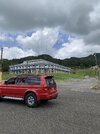
Here are some pictures of the analizer results with the rear gate opened ( I forgot to take a picture of gate opened )
First picture is with the gate opened and with the meter and amplifier in line. Second one is only cable and antenna and gate opened. The third one is with the gate closed with a 97.5” long aluminum radial.
Best results are with the radial.
Brandon says: If you have the means to calibrate the unit, do you have an OSL kit that fits the other end of the coax at the antenna end (SO-239) or just one that fits the VNA port? If the latter is the case, that's ok, it just adds a step (measuring coax electrical length).
Answer is: I have the OSL kit that fits the VNA port. When I bought this analyzer, I calibrated it because I read on the instructions manual I had to do so.
More questions...
1) How did you attach that ground strap to the mag base? Did you peel the foil off? That foil had a purpose

which I'll get to shortly.
2) Why not put the antenna in the middle of the roof? If you are going to a competition, that's where you want it. I could see if you were just shootin' the s#!t on the freeway for 10 miles, but for a competition, you really want it in the middle of the roof. I'm going to catch heat for this, but if the ground strap is the only reason for putting it on the back, abandon that plan. You can ground 27MHz without metallic contact.
3) Are you willing to venture outside of your comfort zone and make some serious changes? If so, keep reading...
In order to have a chance at the competition, I would recommend you move the antenna to the center of the roof, but before doing so, we need to do a few things.
Being you have a mount that the coax cannot be easily removed from, we need to measure the electrical length of that coax MacGyver style before we take any antenna impedance measurements. To do this, remove the antenna from the vehicle, remove all antenna parts from the mag base, short the antenna mounting stud to ground with as short of a wire/strap as possible (or, preferably underneath where the coax braid/center conductor are exposed since the foil is already gone), then set it on a stump or other non-metallic surface and see what the lowest frequency is that the impedance is closest to zero. This will be the frequency at which the coax is 1/2 wavelength long. And knowing that, we can calculate the antenna feed point impedance from the impedance measured at the other end of the coax once it is back on the roof, but not yet.
Now we need to talk about grounding... Since you do not want to drill holes, we need capacitive coupling (which works fine, don't let anyone convince you otherwise). I understand your antenna has only one magnet, but for sake of discussion, lets consider a mount that has three magnets (you'll see why soon), each of 3" diameter. That comes out to about 21 square inch magnet surface area. With the average paint thickness of 0.1mm (not considering the dielectric of the paint as that only makes this math better), we have a capacitive reactance of 5Ω at 27MHz. Essentially, a short to ground (now you know what that foil was for
")
). So, if we can use foil tape connected to the ground screw under the mag mount (or plain aluminum foil with two more magnets holding it tightly to the roof) right under the antenna, we have our ground and running that strap all the way to the hinge is completely unnecessary.
Ok, so now we know the electrical length of the coax, we have the antenna positioned properly in the center for best pattern, and we have it grounded to the center of the roof. Now we can screw the whip back on and take a measurement of the antenna itself. Do this at the frequency you intend to use the antenna on, don't center the VNA where the SWR is lowest, we don't really care about that for this step.. Once we know what the feed point impedance is at the antenna (compensating for the coax length we measured earlier), we can make adjustments and design a matching solution based on math rather than trial and error. Once we have that number , we can talk about what needs to be done at the antenna itself to get the SWR down.
Ill stop here for now. Are you still on board with the process?