• You can now help support WorldwideDX when you shop on Amazon at no additional cost to you! Simply follow this Shop on Amazon link first and a portion of any purchase is sent to WorldwideDX to help with site costs.
  • A Winner has been selected for the 2025 Radioddity Cyber Monday giveaway! Click Here to see who won!

RCI RT-1 MOSFETs WTF?

Snap cap, idk what that device is, but I believe someone stuffed it into one of these, likely for some tacti-cool effect.

Screenshot_20240103-160518.png
 
I see a video on yt showing someone installing one, 2 wires near the pass modulator. Interested in what's inside that thing, maybe another post instead of hijacking this one. Sorry nomad, carry on sir.
 
Likely a diode/resistor NPC modification encased in epoxy with a extra wire that connects to nothing inside.
Most look like this.....
Or the original that looked like a red firecracker.View attachment 67023

Oh, that's gimmicky, but mildly interesting nonetheless. The video I saw looked like it had a pot on it, if so, could be someone else's idea to replace the resistor in that NPC deal so they can say "it's not like the regular NPC and costs more because it's better and your buddies will be jealous, cash only please, no refunds!"
 
Gents, I am fully aware that this is an old thread. However, since my question is about the bias current setting for the RT-1 finals (Q47 and Q48) as well as the driver RT-1 (Q49) I thought it would be good to just continue in this excellent thread. My radio on the bench is the Ranger RCI-69VHP with the same board as in the RCI-69 base. Board is EPT690012D.

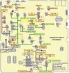
I have attached schematics for the RCI-69VHP in PDF-format.

One of the final RT-1:s blew when I was setting the RCI-69VHP for tuning. (Removing TP-8 jumper and measuring current on the positive power supply feed from my power supply going in to RCI-69VHP.)

I guess that when I had desoldered the gate leg of both Q47 and Q48 I must have shortened the leg of Q47 against the chassi without seeing it and when I turned on the power.... pooofff! Sigh....

Anyway, not a big deal since I just recently received 20 pcs of the IRFZ24NPBF and I was going to replace both final RT-1:s with a pair of matched IRFZ24NPBF (using Peak Electronics DCA75 PRO analyzer). It was interesting to see how big variations on the gate voltage thresholds I could see. The DCA75 shows the gate voltage threshold with three decimals so I was able to find a couple of pairs that had the same threshold voltages down to the third decimal.

I have read through the excellent procedure description in this thread and in the other threads as well, for example
"RCI 69 base": https://www.worldwidedx.com/threads/rci-69-base.253568/
"RCI 2950DX-6 Alignment Specs for Board EPT695016A":"https://www.worldwidedx.com/threads/rci-2950dx-6-alignment-specs-for-board-ept695016a.269489/
"To anyone who has adjusted the bias on an Anytone 6666":
https://www.worldwidedx.com/threads/to-anyone-who-has-adjusted-the-bias-on-an-anytone-6666.258304/

I'll try to summarize the steps here to verify that I have understood the procedure correctly:

1. Radio powered off.
2. Remove jumper TP8.
3. Desolder the gate legs for both finals (Q48 and Q47). Looking from the component side it is the right leg.

4. Power on radio. Make sure mic gain is at minimum and put mode switch in USB or LSB. Also make sure the external power pot is at maximum.
5. Measure the gate voltage at either Q48 or Q47 (TP8 jumper still removed). I clip on the positive lead of my tiny hook probe to the soldered in jumper (just a wire) that connects gate Q47 with gate on Q48 and the negative lead to the chassi.
6. Turn VR10 so that it has maximum resistance = lowest gate voltage.

7. Power off radio.
8. Solder back the gate legs for both finals.
9. Connect amp-meter in line with power supply to radio that can handle 20 A measurements.
10. Power on radio with same settings as in point 4 above.
11. Let the radio sit for a while to get it warmed up and make a note of the current the radio draws in RX while letting it warm up for a couple of minutes. This is what I understand is called the "idle current" in the discussions in this thread and the other threads. TP8 is still removed.

12. Now key up the radio in TX and verify that the current draw is below for example 3A, which is the max current allowed for my more precis digital voltmeter HP 34401A.
13. If current draw is below 3A, unkey TX and power off radio. Disconnect the "rougher" amp-meter and replace it with my HP 34401A that can show many decimals as well has mA scale.
14. Power on radio and verify that idle current is still around the same levels as seen in 12 above.

15. Now key on TX and start turning VR10 SLOWLY until mA draw jumps up 100mA. I guess it should be 50mA per RT-1 final so 100mA in total.

16. Now turn off radio again and remove the amp meter from the power supply line and connect it in-line with a 2-pin connector on TP8. The pin towards the finals connects to the negative lead of the amp meter and the one closest to the front of the radio will be the positive lead.

17. Turn on radio and key up in TX. Now adjust VR12 so that the current draw in TX increases with 50mA. This is where I get lost a little bit since in various comments I have seen to adjust to 100mA due to pre-driver and driver but looking at the schematics the VR12 is connected only to the driver transistor Q49 so I thought I should adjust VR12 for a 50mA TX current increase?

18. Power off radio and remove ampmeter and put back jumper on TP8.

19. Turn on radio and verify RX and TX works as it should.

All this assumes of course that there is no other faults with the radio and that it is correctly aligned on other stages. For example SSB carrier balance must be properly set so that the output power when keying in USB/LSB is as low as possible. Adjustment point VR6.

Have I described the whole procedure correctly or am I missing something or doing something wrong here?

1758547592983.png
 

Attachments

I'm hard-pressed to see that you missed anything. But I do remember RCI telling me about ten years ago to set MOSFET idle current to 10 mA. per final/driver. This was in response to 2995DX radios blowing up IRF520s a week or two after replacement. Just how that advice might apply here is anyone's guess.

It did stop the short service-life problem.

Life was easier when they gave you a removeable jumper board for reading idle current.

73
 
But I do remember RCI telling me about ten years ago to set MOSFET idle current to 10 mA. per final/driver.
Yes I agree, that would be the safest starting point.
I'll start with that idle current and verify output power.

This RCI-69VHP sounded perfect on AM and FM but SSB was just really bad and garbled sound and quite impossible to read. It will be interesting to see if SSB modulation gets more readable after I have tuned in the idle currents to more proper levels (and that I now have a pair of perfectly matched RT-1:s / IRFZ24NPBF).
 
While searching the web for info and videos for adjusting bias for both driver and finals in MOSFET-based radios I found this excellent 9 year old Youtube video from one of my favorite ones, MikesRadioRepair. He uses the amp meter method but also a spectrum analyzer to bring down harmonics as much as possible. Interesting to see that when the harmonic that he monitors in the video is at its lowest position the two finals draw together approx. 125 mA, so 75mA each and the driver was drawing 50mA.

Video can be found here:
"Magnum Delta Force driver and final bias adjustment using spectrum analyzer"

So a good starting point seems to be around 50mA for each RT-1 / IRFZ24NPBF and the fine tune the bias with the SA-method as well. I'll try out that the coming weekend.
 
here's a snip of the schematic for anyone wanting to play along.

1758736356659.png

This is for the 69 base.

This shows that VR12 is for both pre-driver and driver, and VR10 is for both finals.

so it would seem that it's correct to set each of them for 100mA above quiescent current, but Nomad has me wondering.
Nomad would you really set each of these VRs for 20mA?
LC
 
I usually use my bench supply that has an ammeter to set the bias. First I turn all bias adjustments off to zero volts. Then while watching the ammeter, I slowly turn one up while keying the mic in SSB with no audio. I find the point where the current jumps up, this means the transistor is turned on. Then I slowly turn it down until it turns off. Then turn it down slightly more and make sure that it turns off when you unkey. Then I usually go through all the adjustments twice. Once it looks good, I will start talking on it to bring everything up to temperature and verify that they still turn off after they get hot. I am not looking for a specific number, just that it turns off when unkeyed.
 
  • Like
Reactions: Crawdad
But if you turn the bias down while in TX to turn the MOSFET off then you wont get any power during TX?
That is correct, the bias is supposed to keep the transistor right below it's turn on threshold so the side band signal will turn it on right away. Without bias on ssb, the turn on time for the positive going signal is too long and will cause the transistor to miss part of it. AM mode has a carrier signal that keeps the transistor on so it is not an issue in this mode.

Edit to clarify:
With the bias all the way down, it will still produce power. It will just sound choppy on ssb.
 
Last edited:

dxChat
Help Users
  • No one is chatting at the moment.