Thanks I appreciate the info, I think it will work for what I need, mobile use only. I got lucky that it works great.
Looks like a 150 watt amp and if it works, that was a good deal.

You are using an out of date browser. It may not display this or other websites correctly.
You should upgrade or use an alternative browser.
You should upgrade or use an alternative browser.
-
You can now help support WorldwideDX when you shop on Amazon at no additional cost to you! Simply follow this Shop on Amazon link first and a portion of any purchase is sent to WorldwideDX to help with site costs.
Can anybody Help Me ID This Amp?
- Thread starter TopShot1
- Start date
It's a clean amp - not too many with 1446's dated 1998 or 1999 that are still original installs today.
Its' from an earlier time - funny thing is, many amp users often go back to these and wish for the old days again.
Count me as one of them...
That's nearly 20 years old - Caps might need work later - how late? I don't know.
If it works - for $50? You can't find too many places selling 1446's for less than $30 new just for 1.
So not to sound too preachy, just keep power down on the radio driving it. Whether it's a Cobra 19 Plus or a RCI 2950 - don't push it hard, the Bias follows the "10-ohm" rule and if you drive it hard, it's gonna' smoke. So if you're thinking "Competition" .. .DON'T! This things worth a lot more alive than dead. That means limiter in place and not too much swing - these are "low drive" amps and have a narrow window of RF-power swing for best linearity or quality reproduction without the "pinch" or FM'ing many a user pushes these thing into and ruins the effectiveness of having an amp without having to draw attention to yourself.
If you look carefully - it's already seen some abuse. The 10-ohm resistor for the typical Class C bias region that these things usually run is a little cooked. Nothing serious yet, but indicates someone drove it pretty hard already. Be kind to it, you may need this thing someday.
It's not anything new when it comes to platform, in the late 80's into the 90's Lou Franklin published a set of plans and suppliers and even offered "build your own" kits using layouts similar to what I see inside that thing. You put it together, you make it work, so someone found a way to build the networks vertically that cleaned up the layout from the typical "slant 60 degree" coupling that Texas (Outcomm) led the way on for many "Copycats" followed because of board space and a place for mounting a tuning cap to improve the coupling (loose term). Palomar was one of their closest competitors - and they too found ways to make their amps "unique" if not in design - in function - as a selling point. Texas Star had their row upon row of holes for switching with lots of buttons - lighted buttons. Palomar used a relay for switching instead of switches but in doing so limited their abilities but had reliability (took some fun away from playing with it).
I wouldn't put it past someone if they hybrid designed this amp kitbashing a Lou, Palomar and Outcomm design together - Only Lou would have provided more for the AB-biasing as he favored them in SSB. It looks like this board had been "etched" with an overlay for one to install a biasing scheme of SSB and the delay it would need. Palomar chose SD1446 - while Outcomm usually used the Motorola sets or even Toshibas. (Referring to the 10-ohm rule).
I wanted to compliment you on the pics, they make excellent backgrounds for Amp enthusiasts. You're choice of apertures and depth of focus was excellent - clean shots with good detail.
May not be a "matched set" per year dating alone - but what strikes me is the vertical layout and what appears to be that the winds are below the board as pass thrus.
I used to hang out using Newsgroups - Lou had a lot of followers and he also had his share of competitors - but I think - I feel - I believe - that he would have wanted you to enjoy the amp for what it is, not just a wheel chock or a paperweight or some would call "footwarmer" but to each their own - he wanted people to learn radio - so it would (make or) keep some sense of respect and honor amongst those that would ride the grey line and violate a law, but earn a right to wield a power (that came with it) used responsibly. Sure it may violate a law - but earning and learning about radio by building and using amps responsibly - is a moral issue that many forget to remember that others around them see those actions. Be careful with it don't abuse it - you may find them using it against you someday.
You have a tool - give it some respect - provide for it's needs. It can, and possibly will, outlast the radio(s) you use to drive it if you know what you are doing.
Just be careful - install it with care, use protection (fuses, good antennas and mountings, good quality coax and connectors) - you may find them as well as the amp are a good investment.
Enjoy!
:+> Andy <+:
Wow...Thanks for all the great info Handy Andy !!
I was heavy into CB back in the 70's and learned a lot of respect for the hobby from the good guys back in the day, I was in my teens then. So I have a very respectful nature when it comes to good equipment and taking care of it. Still the love the Golden Eagle bases.
It won't be worked hard, I use an amp the way it was intended, to be able to reach out when you need to, not to be the loudest, over-modulated and obnoxious idiots that are out there now....I guess they have always been there. I still like the long nightime talks like I used to do back in the day, there are still some of those people out there.
73's and 88's
Well, thanks for the return in kid words!
The amp may need a little tweak from you as far as some help to keep it sounding clean.
I noticed that for Class C amps need some feedback but this is up to you on it. Lou and others would have said pretty much the same. Run it any way you wish, but if problems occur - it may cost you more for the repair than to simply buy a new one.
I'll post some stuff once I have some pics to show you what I want you to know about saving the amp...
Well, All I've got is a Texas Star that's left over where I can even supply a current photo, but what I wanted to pass along to you was the Amps been "seen" as a Boomer, Palomar now I've located a "Blue Thunder" - no schematic but located here Click here to see this at CB Tricks
No schematic, but at least the photo shows the "vertical transformers" again mounted thru the board, and if you noticed the layout - the Transistors are different but the coil layouts diodes used are strikingly similar - as if one was the template to the other.
Which raises the flag of "a backup plan" - more than likely this amp was made for "comp" or "Stomp" type of things - but when you review the work done to it and only a slightly toasted 10-ohm resistor - you need to step back and realize this one was made not just as a backup but a numbered list of ones they've done.
Put it in line - do the job and leave quickly.
So it doesn't appear to be made for SSB, but uses the board of one - so they did bias it a little differently. This one uses a 51 ohm input resistor to the input core winds that tells me that the amp was more "hand tuned" to provide a low SWR into something they wanted to keep - the radio cost more that the amp was worth.
I hope I'm wrong on the AM ONLY theory - the only way we'd be able to prove otherwise if you took it out and tried it on SSB - that may explain the 51 ohm resistor - for peak 12W that can hold it well - just not 12watts continuous. Your amp will "click" on and will take a moment or two (in seconds) to unkey. That means it was an auto mode one - it was made for a SSB radio.
It's why I need you to look at the link I provided - it may answer your questions far better.
After seeing this one, I got a little lost in a memory - a painful one - what hurts the most, and was always a "trademark" that earlier Palomars were notorious for and for how Lou "dug into them" about their quality - can't print it here, but I do notice the amp does not use a negative feedback system.
So, the "war" of words spilled into the RF realm as "prove it" became more of the norm as these worked into that realm as they called it "Watergate" to prove one design was better than the other. Literally a showdown.
So the one you've got was one someone kept as a spare - it's transistors are not a "matched set" which is probably why the 10 ohm resistor got burnt - but they kept it as a template and working model for "just in case".
IF you want to keep that amp working right, you're gonna' need to use something to keep the amps spurious emissions from killing it outright.
Keep the 51 ohm resistor in there, Palomar used 27 ohm. (Hint: SSB)
Bias? SD1446 should use 22~27ohm where they tuck under the vertical coupler now - but for "tight work" as in compress the RF and Audio on the carrier without too much swing - they used the 10 ohms for the "Pinching" effect of FM-ing intentionally - so they'd push it this hard to try to be heard in a pile up. That may explain the difference of 150 ohm versus the 10 ohm...High Med Low power switch stuff...
The Base Bias - seems right - 27 ohm or so - so this one and the Thunder match. Thunder has the SSB - but note the layout so you may have an "Auto" versus switch -
Builds up the heat running it like that so they "temperature compensated" using diodes. Pretty much a standard method of keeping amps stable but should never be used as a stand alone - it'll need to be swamped with a low-value - say 18 ohm - resistor to bypass the diodes own tendency to leave a residual current behind its' cathode to keep the transistors more "on" than "off" and also more sensitive to stray residual currents.
At least that is what I've seen done to ordinary amps - simply run them more into class C by changing the 150 or 270 ohm to 10 ohm - increasing power out - and the diode to keep the bases forward biased when things get loud (as if RF floating about).
When it came to antennas, Amps are the last line of defense but don't have output networks to handle poor SWR of 2.5 or greater - many blew up with less than 1.7 SWR.
So, install, use and keep a good quality antenna system on that amp too...
These amps were put together to be disposable. They sacrificed the amp to save the radio - by using a 51 ohm resistor to reduce the input of the radios' own RF going into the amp - by showing (fooling) low SWR - a single 51 ohm resistor would be easily get burnt up by a bigger radio running itself full tilt- into something that small - so they purposely "lowered SWR the Radio sees" by padding it with a SINGLE 2W resistor of 51 ohms versus using 2 - 100ohm 2W units instead.
Makes no sense to put a big high-powered radio into this - it would blow up the radio once the input padding resistor popped open like a fuse...so they kept it small...
That way, the radio, whichever one they would want to use would then poke along just fine while the amp did all the work. But the 51 ohm only dissipates 2 Watts so the radio they used was not a big one, just something that had, more than likely, a 2078 or 1969 final nothing more than perhaps a 8 watt TRC-465 can drive this thing all day without breaking a sweat....
I've had to re-do some "oldie amps" people wanted to keep - shame that many other amps "gave their lives" for a "Pump up the Volume" moment.
Anyhoo, will add more
Hope the photo gives you a better shot at understanding what you got...
Regards!
:+> Andy <+:
Last edited:
Thanks, If there are ways to protect and improve the amp, i’m all ears.
Just use the amp and be happy.
Thanks again for the explanation, sounds like this was designed as a driver for a bigger amp downline if I understood you correctly.
I am NOT a tech unfortunately, so hopefully this amp will work being driven by a 2 watt carrier and low swing as a standalone amp, with no mods.
I for one really appreciate the helpful nature of Handy Andy.
I am NOT a tech unfortunately, so hopefully this amp will work being driven by a 2 watt carrier and low swing as a standalone amp, with no mods.
I for one really appreciate the helpful nature of Handy Andy.
This is about as close as I can get to your amp - minor details and perhaps a cap or two a farad or two off or even missing - but hard to locate an EXACT otherwise...

The COLORED portions are what is in the amp now, the HIGH MED LOW Switch? looks like he set up one of the switches' settings to full thrust, as No Holds Barred - review your switch layout and find the wire that identifies these resistors - because for the 51 ohm to take the place of original 27 means he had to adjust for that input level by shunting more RF to ground.
This takes It to a tricky realm. So it appears to me the mods make this a custom amp for the individual and their style of radio output...So that I strongly urge you to review the amp schematic and realize the SWR of the amp to the previous users was an important factor - so they dissipated more RF and reduced the input level of RF to "make it a swinger" than it should be - hence the toasted resistor.
Review and proceed at your own risk.
Regards!
:+> Andy <+:
back in 2000 to 2004 I was buying and selling a small 250 amp that had the 1446 pills in them. they look about like this one. I was paying 65.00 each and just 10.00 to mail me 3 at a time. they would do 175 watts on AM high power setting and about 250 on SSB. I sold a bunch of them and only charged 100.00 and that included setting the radio to run the amp. that was even sales tax included. a few guys are still running them as long as the dead key was around 2 watts. some blew the pills in them by putting them behind a high power dual final radio and not matching them up with the radio. those were tuff little amps.
Last edited:
And if it begins to drop out on receive, this probably is not a case of a relay that is "sticking" as folks like to say.
When you lose your receiver signal when you unkey the readio, it's more likely the tiny relay used for the preamp has a poor connection on one or both of the "off" side contact points. This is the side of that relay that carries your receiver signals from the antenna when the preamp is switched off. If a small "tap" to this relay restores the receiver signals to the radio when they drop out, here is the fix we use. Gently cut out the two lever arms. If you have some thin bare wire handy, that's what you see in the pic. If you don't, extract two strands from a stranded power lead or speaker wire. It's usually thick enough to carry the radio's barefoot transmit power okay. Jump the contacts as shown.
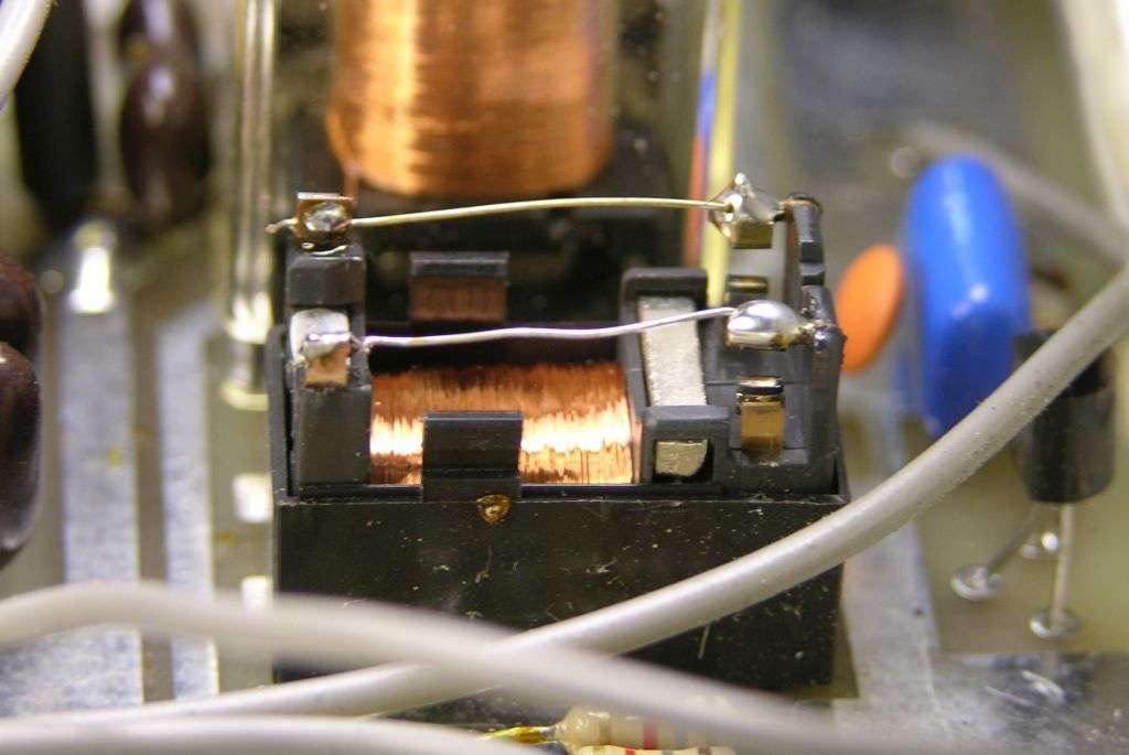
Lots easier than extracting the circuit board from one of those.
73
When you lose your receiver signal when you unkey the readio, it's more likely the tiny relay used for the preamp has a poor connection on one or both of the "off" side contact points. This is the side of that relay that carries your receiver signals from the antenna when the preamp is switched off. If a small "tap" to this relay restores the receiver signals to the radio when they drop out, here is the fix we use. Gently cut out the two lever arms. If you have some thin bare wire handy, that's what you see in the pic. If you don't, extract two strands from a stranded power lead or speaker wire. It's usually thick enough to carry the radio's barefoot transmit power okay. Jump the contacts as shown.
Lots easier than extracting the circuit board from one of those.
73
Last edited:
Well I agree with everything except the DEI transistors. Too cheap to get fully tested and properly matched HG's from RF parts that seriously lowers the chances of getting a lemon. Not like he is ordering these by the Gross! That said he could even spring for Toshiba 2SC2879 or Motorolla MRF454 also pretty well checked out and tested by RF before shipping....temp tracking bias
do away with the Hi/Med/Low
correct the transformers
reinforce the B- rail
resurface the device mounting
Fans, 1U computer fans, two deep, full width, full shroud.
construct/add external LP filter
A "real" supply
then replace the transistors with DEI because the Toshibas are dead ...
")
dxChat
- No one is chatting at the moment.
-
@ Wildcat27:Hello I have a old school 2950 receives great on all modes and transmits great on AM but no transmit on SSB. Does anyone have any idea?
-
-
-
dxBot:63Sprint has left the room.
-
dxBot:kennyjames 0151 has left the room.