
You are using an out of date browser. It may not display this or other websites correctly.
You should upgrade or use an alternative browser.
You should upgrade or use an alternative browser.
-
You can now help support WorldwideDX when you shop on Amazon at no additional cost to you! Simply follow this Shop on Amazon link first and a portion of any purchase is sent to WorldwideDX to help with site costs.
Regency Range Gain low modulation
- Thread starter Champo
- Start date
Sorry that's a typo. Too much copying and pasting between here and emails. 184vdc is correct at pin 1. 159 is an erroneous number. I also swapped tubes from V2 and V8 with no change just to throw that in the mix. I'll have to lift one leg of R66 later tonight.Champo,
In your earlier post, you reported measuring 184 volts to pin 1 of V2. Now you are measuring 159 volts at the same point.
What has changed?
What does R66 measure out of circuit? (1 lead lifted)
73
David
So the voltage issue on V12 Pin 2 appears to be related to the RF choke L16. I have -16vdc going into it but 9vdc on the other side. Is it safe to assume that it's toast and is there a replacement someone can recommend? Thanks!
EDIT:
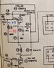
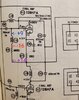
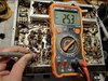
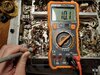
I had to add this because I've never observed this before but I'm getting +14vdc before the 6.8k resistor, -16vdc after it and then +9vdc on the other side of the rf choke???
EDIT:
I had to add this because I've never observed this before but I'm getting +14vdc before the 6.8k resistor, -16vdc after it and then +9vdc on the other side of the rf choke???
Attachments
Last edited:
I also forgot to add that I wonder if the V2 pin 1 value of 260vdc isn't a typo duplicated from V2 pin 6. If you look at the other 6AN8 (V8) Pin 1 is 180vdc....just about what I'm getting at V2 pin 1 (184vdc). V8 Pin 1 is fed 270vdc through a 33k resistor to get 180vdc. In my case getting 174vdc. V2 Pin 1 is 270vdc fed through a 22k resistor getting 184vdc. The 22k resistor is good. Let me know if my logic is flawed? Thanks!
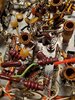
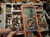
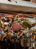
I figured there might be some skepticism about the voltage inversion so here are pictures showing the values when keyed. As you can see there is a negative voltage inversion through the 6.8k resistor and then a positive inversion through the RF choke. The Sam's shows that there should be a negative value at the tube pin which isn't occurring. The only thing I can think of is that they created a negative impedance converter that isn't working properly. The reason I suspect this is test point #1 is positive and the expected value per Sam's at V12 pin 6 is expected to be positive, which it is. The only thing between test point 1 and V12 pin 2 is the 6.8k resistor and the RF choke however they're expecting that value to suddenly be negative, which it is at test point 2, before becoming positive again. The curve ball is that pin 2 is tied into the A20 adjustment. Disregard the values themselves. The values are affected by the location of the loading knob and it was in a different position.
Attachments
****EDIT****
I compared the wiring diagram in the Owner's Manual to the Sam's and the Sam's is indeed wrong. I figured I'd leave this post in case someone else encounters this issue in the future.
I just realized that I forgot to hit post yesterday regarding V7 (6CM8). It is not wired as stated in the Sam's. Here is what is different:
So V7 is kind of funky but I figured it out. Pin 7 is the only odd man out. Everything else is good.
1 and 6 are reversed
2 and 9 are reversed
3 and 8 are reversed
7 shows it should have the same leg as 6 (which is wired as 1 《150vdc》) but it is actually getting 15vdc from the square 30mfd cap. As a result the keyed value is half of the Sam's ( 17.2vdc vs 30). I'm not sure if it is relevant or not. Below are the wiring descriptions and new numbers.
V7
Pin 1 : 176.5vdc from 30 mfd cap (triangle)- tied to R4 modulation pot
Pin 2 : 15vdc from 30mfd cap (square) to 10 meg resistor
Pin 3 : runs to squelch knob
Pin 6: 1 Meg resistor to V8 Pin 8
Pin 7 : 15vdc from 30mfd cap (square) to 82k resistor
Pin 8 : 4.7k resistor to ground
Pin 9 : 47k resistor to 3.9meg resistor and audio line to mic socket.
V7
Pin 1 : 80 = 75
Pin 2 : 3 = 3.6
Pin 3 : 8 = 8.5
Pin 6 : 15 = 15
Pin 7 : ? = keyed 17.2, unkeyed 15.5
Pin 8 : .8 = .9
Pin 9 : 0 = -.1
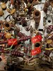
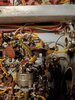
It all looks original. No modifications appear to have been made to the radio.
I compared the wiring diagram in the Owner's Manual to the Sam's and the Sam's is indeed wrong. I figured I'd leave this post in case someone else encounters this issue in the future.
I just realized that I forgot to hit post yesterday regarding V7 (6CM8). It is not wired as stated in the Sam's. Here is what is different:
So V7 is kind of funky but I figured it out. Pin 7 is the only odd man out. Everything else is good.
1 and 6 are reversed
2 and 9 are reversed
3 and 8 are reversed
7 shows it should have the same leg as 6 (which is wired as 1 《150vdc》) but it is actually getting 15vdc from the square 30mfd cap. As a result the keyed value is half of the Sam's ( 17.2vdc vs 30). I'm not sure if it is relevant or not. Below are the wiring descriptions and new numbers.
V7
Pin 1 : 176.5vdc from 30 mfd cap (triangle)- tied to R4 modulation pot
Pin 2 : 15vdc from 30mfd cap (square) to 10 meg resistor
Pin 3 : runs to squelch knob
Pin 6: 1 Meg resistor to V8 Pin 8
Pin 7 : 15vdc from 30mfd cap (square) to 82k resistor
Pin 8 : 4.7k resistor to ground
Pin 9 : 47k resistor to 3.9meg resistor and audio line to mic socket.
V7
Pin 1 : 80 = 75
Pin 2 : 3 = 3.6
Pin 3 : 8 = 8.5
Pin 6 : 15 = 15
Pin 7 : ? = keyed 17.2, unkeyed 15.5
Pin 8 : .8 = .9
Pin 9 : 0 = -.1
It all looks original. No modifications appear to have been made to the radio.
Attachments
Last edited:
Champo,
Have you checked voltage before and after R56? It is tied to tube V8 and appears to be fed by T2 (Blue-White wire). T2 appears to be the source of the voltage to the grid of V12. Tube V8 is labelled "Phase Inverter".
73
David
Have you checked voltage before and after R56? It is tied to tube V8 and appears to be fed by T2 (Blue-White wire). T2 appears to be the source of the voltage to the grid of V12. Tube V8 is labelled "Phase Inverter".
The only thing I can think of is that they created a negative impedance converter that isn't working properly.
73
David
15vdc on both sides. At this point I'm convinced that the problem is at V12. What I don't understand is why I have the correct negative voltage on one side of the RF choke but the incorrect positive voltage at the pin. I tried removing the neutralizing gimmick (unfortunately I destroyed it in the process) with no change. I also tried bypassing the RF choke and you lose the negative voltage all together. My gut tells me it's something with A20 since that's the only other thing tied into pin 2 of V12. Pin 7 and pin 2 are tied into one another through A20 and pin 7 has the correct voltage but pin 2 does not. My limited understanding of how tubes function in circuit doesn't help though so it could be something else at V12.Champo,
Have you checked voltage before and after R56? It is tied to tube V8 and appears to be fed by T2 (Blue-White wire). T2 appears to be the source of the voltage to the grid of V12. Tube V8 is labelled "Phase Inverter".
73
David
Perhaps someone can edumacate me. Where does a negative grid voltage originate from or how is it created/injected? The reason for the question is that that's where the problem lies in this radio. The grid (Pin 2 of V12) isn't going negative so it isn't stopping the flow of electrons.
"Because like charges repel, a negative charge on the grid (lots of excess electrons on the grid) repels the negatively charged free electrons trying to flow from the cathode through the grid to the plate. But a positive charge on the grid (scarcity of electrons) allows the free electrons to pass through the grid. If you fluctuate the electric charge on the 'control grid' you fluctuate the current flow between the cathode and plate. This effect is used as a signal amplifier by applying a low level guitar signal to the grid which controls the much larger flow of free electrons between the cathode and plate."
This is the key...
Champo,
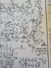
I have the diagram you posted as well as the Sams (#5) for this model. Isn't the schematic you posted from the Range Gain II? My Range Gain is still in the case and I haven't looked at it in a while but the 2 schematics (Sams and "Original") are very different.
If the tube voltages for V11 are very close to the Sam's, I still say that without A17/A18 (L5) & A19/A20 (L15) being properly adjusted (TX Alignment step 1), you will not see the correct voltages at V12.
73
David
Last edited:
Thank you for the reply. No the diagram I posted is from the Regency Range Gain owner's manual and it is how mine is wired particularly related to V7 which is completely different than the Sam's. I think there are considerable errors in the Sam's when it comes to V7's wiring. For the most part though my voltages line up with what the Sam's says with the exception of V2 pin 1 and and V12 pin 2.
In regards to pin 2 of V12 your explanation makes sense. I ordered a VNA so hopefully I can align the Regency (if I can figure out the VNA) and correct V12. As for V2, I think it might be a typo or duplication from V2 pin 6 because I'm not sure how you would end up with the same voltage value when you're feeding the pins the same voltage but one is passing through a 22k resistor and the other through a 1k (pin 6). I could be wrong however.
The other 6AN8 tube (V8) is fed 270vdc to pin 1 through a 33k resistor ending up with 180vdc which is closer to what I'm getting at V2 pin 1. Regrettably the owner's manual has very few voltages so I can't cross reference that particular value. Let me know your thoughts regarding V2 pin 1. Thanks!
Jacob
Champo,
I'm afraid I cannot offer any other "hints or kinks" in regards to this issue.
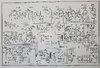
I have the same schematic you posted and it is vastly different from Sam's CB-5.
I have been following along with the Sam's manual-where according to Sam's;
Valve V12 is the final amplifier tube and is a tube type 12BH7A.
Valve V2 is the receive/transmit oscillator and is a tube type 6AN8
According to the factory print you and I have;
Valve V6 is the final amplifier tube and is a tube type 12BH7A.
Valve V12 is the receive/transmit oscillator tube and is a tube type 6AN8.
There are many inconsistencies between the 2 schematics. Makes me think if the "Factory" schematic is true to your example, the Sam's manual Alignment Instructions cannot be trusted.
My Regency Range Gain is in the "To Do" pile and I have no plans to start on it in the near future. Previous thoughts have been to gut the chassis and install a modern (no tube) chassis in the case just for something different. So it is in the "To Do" pile when time allows.
73
David
I'm afraid I cannot offer any other "hints or kinks" in regards to this issue.
I have the same schematic you posted and it is vastly different from Sam's CB-5.
I have been following along with the Sam's manual-where according to Sam's;
Valve V12 is the final amplifier tube and is a tube type 12BH7A.
Valve V2 is the receive/transmit oscillator and is a tube type 6AN8
According to the factory print you and I have;
Valve V6 is the final amplifier tube and is a tube type 12BH7A.
Valve V12 is the receive/transmit oscillator tube and is a tube type 6AN8.
There are many inconsistencies between the 2 schematics. Makes me think if the "Factory" schematic is true to your example, the Sam's manual Alignment Instructions cannot be trusted.
My Regency Range Gain is in the "To Do" pile and I have no plans to start on it in the near future. Previous thoughts have been to gut the chassis and install a modern (no tube) chassis in the case just for something different. So it is in the "To Do" pile when time allows.
73
David
Let me start by apologizing as I can see how confusing my post has been now lol! I've actually been working from the Sam's so my tube references have all been related to the Sam's tube labels. I've continued working from the Sam's because it has voltage and resistance values that the owner's manual lacks ( though possibly wrong) and it's actually easier to follow. For the most part it seems to be correct with the exception of V7 (6CM8). This is where the largest discrepancy is that I've discovered anyways. There could be others that I've missed. My resistance and voltage values were all wrong at V7 and it wasn't until I really took a hard look at each pin circuit that I realized it was not wired the same as the Sam's. Once I flipped the pins and checked the values they worked out correctly. Later I had that "duh" moment and remembered that the owner's manual had a wiring diagram in it and it confirmed my suspicions. Beside my issue at pin 1 V2 (6AN8) and pin 2 V12 (12BH7) the vast majority of voltage and resistance values are correct or very close. There are a few exceptions.Champo,
I'm afraid I cannot offer any other "hints or kinks" in regards to this issue.
I have the same schematic you posted and it is vastly different from Sam's CB-5.
I have been following along with the Sam's manual-where according to Sam's;
Valve V12 is the final amplifier tube and is a tube type 12BH7A.
Valve V2 is the receive/transmit oscillator and is a tube type 6AN8
According to the factory print you and I have;
Valve V6 is the final amplifier tube and is a tube type 12BH7A.
Valve V12 is the receive/transmit oscillator tube and is a tube type 6AN8.
There are many inconsistencies between the 2 schematics. Makes me think if the "Factory" schematic is true to your example, the Sam's manual Alignment Instructions cannot be trusted.
My Regency Range Gain is in the "To Do" pile and I have no plans to start on it in the near future. Previous thoughts have been to gut the chassis and install a modern (no tube) chassis in the case just for something different. So it is in the "To Do" pile when time allows.
73
David
You do bring up an interesting point about the alignment being untrustworthy though. Unfortunately I don't have an alternative so I think I'll use the NanoVNA and follow the transmit alignment procedure and, if unsuccessful, I'll try guitar_199's route of trying to peak for max output. Whatever is holding this radio back is minor and probably staring me in the face but for the life of me I can't find it. All appearances are that it receives well when compared to my other operational radios and sounds alright on air but it is weak. I'm hoping it could be as simple as an alignment because besides that I don't know what else it could be. If it fails to produce results then I'm all out of options. Pretty much the problem is it keys low (3/4 - 1watt) and only swings to 3 watts rather than the 10 PEP. If an alignment can cure both of those ailments then I should be in business...hopefully!
One thing about SAMS is that they usually rewrote the schematics and renamed everything so it becomes confusing when one tries to compare them to the original. Once you understand that and know what you're looking at it's not a problem. They can actually be easier to read than some originals. Since they are rewritten there are mistakes sometimes but you will come across mistakes in originals as well. Also SAMS usually rewrote the alignment procedures too. Another thing is that many radio manufacturers made updates to their radios. They most likely printed revised schematics but most never released them. So there may be differences from the radio you are working on as compared to the schematics that they released. The problem then is what revision radio do you actually have? Tram D201As are like that. There were many revisions but only one schematic released. I once had three TRC 458 Navahos that were built within 2 years (1977-1978) that had different cap arrangements on the bottom side of the board but only one schematic was released. GE Superbases and like radios come to mind with their three versions as well as many other radios. Another problem with SAMS is that usually you don't know what revision they wrote their schematics from. If only one was released that is probably what they used. If many were released such as in the case of the Tram Titan II, the one SAMS used was most likely the current one at the time. The one they used for the Titan II was R2 but there was also R3 and R4 later on due to improvements that were made to the radio.

dxChat
- No one is chatting at the moment.
-
-
-
dxBot:63Sprint has left the room.
-
dxBot:kennyjames 0151 has left the room.
-