• You can now help support WorldwideDX when you shop on Amazon at no additional cost to you! Simply follow this Shop on Amazon link first and a portion of any purchase is sent to WorldwideDX to help with site costs.

Use of capacitor across the leads of stock Taiwan Cobra 148 GTL speaker?

skiman1

Member
Aug 28, 2014
57
25
18
33
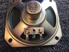
Just replaced an old Taiwan Cobra 148 GTL's speaker that was getting raspy sounding at low volumes with a brand new Workman SA-350 3.5" replacement speaker, did the trick. The old speaker has a small cap across the terminals, (see attached) and the new one doesn't. Does anyone know the reason why Cobra would put these caps in in the first place? The only thing I can think of would be preventing peaks that may damage the speaker or altering the frequency response of the speaker, either adding highs or cutting bass, but figure someone here would know for sure, thanks! Skiman
 

Attachments

  • IMG_2412.jpg
    IMG_2412.jpg
    783.2 KB · Views: 28
Last edited:
  • Like
Reactions: Rebel Outlaw

If I remember correctly years ago I had a Noise Canceling Speaker that had a Noise Canceling push button. I think it just put a cap in line and bypassed it. Try looking up Noise Canceling Speaker Mod. I think cbrepairguy, Doug Mullens from Custom CB Radios had a Youtube Video about a Noise Cancelling Speaker mod a while back.
 
The job of capacitors is to allow only the high frequencies to pass.

Yeah, and when it's in parallel with the speaker, it "passes" high frequencies "around" the speaker, not through it. Marking appears to say "102", which means 1000 pf, or .001 uf.

The capacitance value of that disc cap is small enough to have no impact on the speaker's audio performance. I'm pretty sure it's meant to keep RF voltages off the coil in the speaker, effectively "shorting" those frequencies across the speaker while having no effect on the audio voltages.

73
 
In the case of a larger capacitance value such as 1uf or more, the cap across the terminals (in parallel) of a speaker will roll off the highs. It will function as a “hiss” filter so to speak. It's basically passing the highs to the ground side of the speaker before the speaker itself receives the audio.
 
Looks like I came late to this party...everyone else has Answered this...

upload_2021-11-6_8-13-49.png


The Capacitor is marked 102 which if you remember your capacitor resistor - value multipliers...

The Cap starts out in Pico - and you add "zeros" to the first two digits...

So this 102 - turns into 1000pF or 0.001uF or 1 Nano farad?

Why would it be on the speaker - this way?

Well, it works much like a hi-cut filter - takes some of the high treble and hiss - since they are high frequencies - find the trip thru the capacitor easier than the many turns of coil in the speaker coil core.

You will see this a lot in older radios from "Taiwan" they also used to use a "gasket" as a means to help dampen the rather harsh rattle a upper midrange speaker like this would otherwise color the sound. So they make the smaller speaker a little bigger in "sound" by making the cap and the chamber the cone works it, to lower and improve the fidelity to a point where it is more focused on speech than music.

As said to the group they all rushed in and answered the question - but there's little things that make older systems and CB's so appealing is due to their sound - this is one of those little tricks they USED to do...
 
Well, there's no substitute for proof.

I would just suggest you connect the speaker by itself, then hold the two legs of a .001uf disc up to the two lugs on the speaker while it's playing.

If you can hear a difference when the capacitor's leads touch the speaker's lugs, go for it. Might be a bit less clumsy to solder just one leg of the cap, and touch the other lead to the other lug for an easy A/B comparison.

I'll withhold my prediction for now.

One accurate measurement is worth a thousand expert opinions. Or so said Admiral Grace Hopper.

73
 
The cap we use to roll off high audio frequencies in RCI-made radios is 100 uf. That's 100,000 times the capacitance of that disc cap marked "102".

The reason we'll add that cap to the speaker in a driver's radio is to reduce talkback 'squeal' problems.

Does work.

73
That is a great idea, I am going to try this on my Anytone 6666. This radio has a lot of hiss, I don't know if that's normal for these radios or not. The factory high cut is too much, maybe I can find a capacitor value to make it just right. Thanks!
 
  • Like
Reactions: r carl
This is the basic hi-cut filter circuit they used in my Bearcat external speaker. Note the polarity of the two capacitors in series. That essentially makes those equivalent to a single 110uf non polarized capacitor. IMO I would only apply this and similar circuits to an external speaker. I prefer going the “adjustable tone control method” that’s usually found on the input of the audio amp. Typically this added feature is found tapped into the radio's volume controls center conductor.
Bearcat filter.jpg
 
One of Mike’s videos gives details on the center terminal volume control tap. Since you’re tapping into a high impedance circuit, a considerable lower capacitance value is used, unlike the high capacitance that's used across 8 ohms. Again, use only a non-polarized capacitor in either case. Mike uses a substitution box, great, but for experimentation, an assortment of green mylar film caps is what I grab. I start with .1uf + or – a few values. That should get you into the ball parked range with finding your sweet spot.

 
I was just surprised that with all the documentation out there, the questions about the cap across the speaker is real.

There are radios - not just CB, that use these as a simple "Hi-Cut" for their tabletop and sport event radios - read this as those cheap 7 Transistor Japanese/Chinese radios from the 70's.

upload_2021-11-11_8-47-58.png
  • Retro - talk about old times... - these had used "tweeter" speakers and place them in a box with slot/slits/slats in the opening to allow the sound to resonate and reverberate. By using a design of this "Baffling" system and use of caps to tamp down the tone - you could at least listen to those songs and sports games
  • - so they can acheive the somewhat classic "transistorized" sound the old styles used - Caps across the speaker were for the same board used in different styles - but the cap used was of different values specific to each box for their "sound reproduction".
  • One Drawback, because of this tone filtering system - a lot of the produced energy was lost in the filters - absorbed and sent to ground - lost to help in making the system efficient
  • - these things ate batteries like no tomorrow - and the volume needed to even hear it - the Earphone was the way to use the system without draining the batteries from trying to into a low-ohmic impedance amplifier for the speaker.
Obviously the bigger the box, the more Bass can be made - but to cut off the shrill sound of that tweeter speaker - they have to do something like this...
upload_2021-11-11_8-44-19.png

You guys know this; it's from the radio the OP started this thread about...​
 
The .001uf cap across that 8 ohm speaker was never meant to be hi-cut filter as far as any human ear can detect. If only my dog could talk during an on-off test, maybe he could discern a difference. Conclusion: I totally agree with Nomad. That cap all about bypassing only RF frequencies without affecting the audio.
 

dxChat
Help Users
  • No one is chatting at the moment.
  • @ Wildcat27:
    Hello I have a old school 2950 receives great on all modes and transmits great on AM but no transmit on SSB. Does anyone have any idea?
  • @ ButtFuzz:
    Good evening from Sunny Salem! What’s shaking?
  • dxBot:
    63Sprint has left the room.
  • dxBot:
    kennyjames 0151 has left the room.