• You can now help support WorldwideDX when you shop on Amazon at no additional cost to you! Simply follow this Shop on Amazon link first and a portion of any purchase is sent to WorldwideDX to help with site costs.

102" whip vs the rest

Brandon , I try to answer in order:

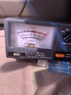
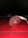
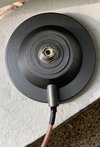
1- I attached the ground strap inside the magnet mount, where the shield is attached. I didn’t peel the foil off. ( see picture )

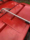
2- I put my antenna on the rear of the roof because in theory it makes my antenna a bit more directional in that location, thus signal should be stronger towards the front. I always taught, antennas located on the rear, making them more directional, on a competition, may have a little advantage over antennas on the center. Otherwise, the center is the best location. Why you say the center would be best on a competition if antennas located on the rear have more directivity ? Please, if I am enlighten me regarding this.

3- Yes, I am willing to make changes. Again, why do I have to move the antenna to the center in order to have a chance in a competition? Why you say “ that coax MacGyver style “ ?

It is easy to disassemble the magnetic mount. When you say: “ short the antenna mounting stud to ground” , do you mean to short the center conductor to the shield ? That is easy. I can do it. All I have to do is to loosen the center nut of the magnet, the magnet will drop and can see the coaxial cable attached to the SO-239.

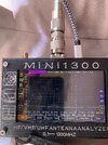
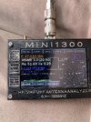
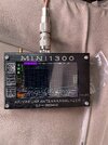
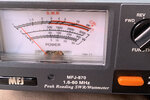
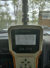
On the Mini 1300 analizer, how do I measure this impedance? Any specific symbol ?

I can follow the other steps you mentioned. And yes, I am still on board with the process .
 

Attachments

  • C042CD55-1193-44D2-8290-4E8F87D69FFE.jpeg
    C042CD55-1193-44D2-8290-4E8F87D69FFE.jpeg
    986.5 KB · Views: 13
Last edited:
I will follow suit and try to answer in order as well. But I should mention right off the top that if you are not reasonably familiar with the functions of your analyzer, we probably shouldn't be trying this. You might consider an antenna tuner instead...

1) If the foil is still intact (and has continuity to the shield???), that's good! But that is still a small fraction of the capacitive coupling you would need to have without using a ground strap. The issue with ground straps, at least ones more than a few inches long, is that the antenna to ground plane capacitance is to the metal closest to the antenna, and having it go into the metal, down the body to the grounding bolt, then back up the strap to the coax shield is essentially a hairpin inductor that puts the voltage on the shield connection at a different potential than that on the metal directly under the antenna (it actually sets up a slot mode wave across the gap, but just imagine its a plain old inductor for simplicity, comes out about the same...)

2) Perhaps I misunderstood how "keydown competitions" work... I figured it was about having the strongest signal in all directions, not just bending a needle on a field strength meter set up in just one direction, but OK.. By all means put it on the back of the vehicle then, because yes, you are correct in that it adds directivity :) All I know is, if I were to hold a competition for best signal, it would involve receiving stations in at least 6 directions and averaging what they all receive. I don't see much point in having a mobile rig with a directional pattern as the roads I drive on are not straight! What good are mobile bragging rights if I lose you when you round a corner??? You may as well bring your base station/beam and set it up in the parking lot. But to each their own I guess....

3) I said MacGyver-style because the proper way to do that is to use a shielded short so common-mode currents don't interfere with the reading, but whatever you can do is what we have to work with. And yes, I meant shorting the shield to center conductor because these analyzers are better at measuring low impedances than high impedances and a half wavelength coax will not transform the impedance (discounting losses)...

But, as I mentioned at the top, if you are not familiar with taking impedance measurements with that analyzer, this will probably end badly (and I am not familiar with that particular unit to offer instruction there). I was prepared to help design a homebrew match to install at the antenna's base, but that requires the measurements to be made with absolute confidence and accuracy. If they are not, the dimensions/measurements I tell you will just make things worse. Do a little studying on your VNA before you bother with any of what I said.
 
When you say the mag mount has an SO-239, are you sure??? My mag mount came with what looked like an SO-239, but with the center having a pin instead of a hole. If it is indeed an SO-239 that the antenna screws into, then you could make a set of calibration loads out of common PL-259 ends and get a good calibration to the antenna input plane (which would give us a really nice reading of the antenna's R±jX values!
 
  • Like
Reactions: Alexis Mercado
I shot a 9 minute video about how I matched my 102" whip, explaining the what for and why for those who wish to better understand the process.

@Alexis Mercado This should give you an idea of the direction I am heading with our recent discussion.


Edit: and this is the SWR sweep on that antenna, under 1.5 over more than the entire 11m band, and thats without cleaning any of the connections in over 5 years :)
 

Attachments

  • antenna swr.jpg
    antenna swr.jpg
    2 MB · Views: 7
Last edited:
brandon here are some pictures of the magnet mount.

I could make a set of calibration loads out of common PL-259 ends to screw them on the SO-239 connector of the magnet mount. One shorted, one with a 50 ohm resistor.Is the open one really necessary with this mount ?
 

Attachments

  • 772A0723-4009-4181-9EAE-390DD512D4E0.jpeg
    772A0723-4009-4181-9EAE-390DD512D4E0.jpeg
    1.4 MB · Views: 5
  • DA0F66CD-D8C9-4F23-8E7B-09D503F3B8B2.jpeg
    DA0F66CD-D8C9-4F23-8E7B-09D503F3B8B2.jpeg
    732.2 KB · Views: 5
Last edited:
  • Like
Reactions: brandon7861
I would say no, it's not necessary to make an open at 27MHz. The little bit of capacitance change not having one will not make enough difference to screw up our measurements on 11m (but don't try not using one on VHF!). When you make the 50Ω and the short, keep leads as short as possible! It often turns out better if you use two 100Ω resistors in parallel for the load, with one on each side of the center conductor to ground.

If possible, find a scrap of metal that you can use to cap off the PL-259's after adding your resistors and shorts so they are shielded, it will make them useful up to about 6m if the resistors are accurate. Foil tape is ok, but soldering on a piece of copper ribbon (or a dime) to close the coax hole is better.
 
  • Like
Reactions: Shadetree Mechanic
I shot a 9 minute video about how I matched my 102" whip, explaining the what for and why for those who wish to better understand the process.

@Alexis Mercado This should give you an idea of the direction I am heading with our recent discussion.


Edit: and this is the SWR sweep on that antenna, under 1.5 over more than the entire 11m band, and thats without cleaning any of the connections in over 5 years :)

Thanks for sharing this, what is that stud mount with the insulator built-in, and where did you get it?
 
Thanks for sharing this, what is that stud mount with the insulator built-in, and where did you get it?
I got all the parts (minus the tinned copper wire used for the coil) at Radio City in MN before they closed their doors :( The triple mag base had a threaded connection like the one showed on Alexis Mercado's magnet (except mine had a reversed sex connection... but there is a center conductor through the middle of the nylon) so I disconnected the coax from the bottom so that it acted like an insulator. I have tried to find a source of those (because I wanted to market my design) but couldn't find them anywhere. I couldn't even find the fiberglass ones used on those factory-made antennas with the flat brass loading coils :( I looked everywhere. If you find a source for them, please let me know!!!!
 
  • Like
Reactions: Shadetree Mechanic
Here some other pictures of the Mini1300 analyzer and the SS whip with 15” extensions
( adapter + 10” shaft + spring) mounted on the rear of the roof. I have to lift the rear gate to keep SWR controlled around 1.3 If not, SWR get close to 2.0.
 

Attachments

  • 1378EEFB-A9B2-4B33-9301-D29B5B6BD7CA.jpeg
    1378EEFB-A9B2-4B33-9301-D29B5B6BD7CA.jpeg
    2.2 MB · Views: 17
  • 33E3DED8-2ADE-4B42-8366-885854391FB5.jpeg
    33E3DED8-2ADE-4B42-8366-885854391FB5.jpeg
    1.4 MB · Views: 19
  • BB38228E-0FDA-405A-9437-1D50322094F3.jpeg
    BB38228E-0FDA-405A-9437-1D50322094F3.jpeg
    1.9 MB · Views: 16
  • 5D81D433-7FB1-429A-A27A-04EC6D402D32.jpeg
    5D81D433-7FB1-429A-A27A-04EC6D402D32.jpeg
    1.8 MB · Views: 17
Hi again brandon. Here are some other pictures with a radial attached to the ground strap. I could get a 1.0 SWR. The radial is 99” long. SS whip is 117” long.
 

Attachments

  • 144A7EA8-351F-4996-B79E-BBCF624B9D53.jpeg
    144A7EA8-351F-4996-B79E-BBCF624B9D53.jpeg
    2.1 MB · Views: 13
  • D2FF3B53-8B83-451C-B39C-47D3F58A298E.jpeg
    D2FF3B53-8B83-451C-B39C-47D3F58A298E.jpeg
    4 MB · Views: 13
  • 758CA326-0B0F-4ED4-BBFC-588B64CF37A3.jpeg
    758CA326-0B0F-4ED4-BBFC-588B64CF37A3.jpeg
    2.7 MB · Views: 11
  • F253413D-1234-4EF4-A625-A6F843A536FB.jpeg
    F253413D-1234-4EF4-A625-A6F843A536FB.jpeg
    1.6 MB · Views: 12
  • 2E520D6F-E830-48C1-A4BA-B2D3FA7FB57E.jpeg
    2E520D6F-E830-48C1-A4BA-B2D3FA7FB57E.jpeg
    1.1 MB · Views: 14
Last edited:
So far nobody has mentioned capture area of antenna. This relates to radiation efficiency ,the 102" whip has a rating near 100% a the truth chart in my book by Wlliam Orr on CB antennas. Shorter whips have varying numbers on the chart but none of them are as high as the quarter wave. Its physics and that does not change
 
How well you hear depends on the radiation pattern of an antenna. A 102" whip, a 1/4 wave length antenna, has one pattern. Longer antennas (to a point) tend to have larger patterns, or patterns that cover more area. Antennas that are shorter than the 1/4 wave but use a loading coil to make it 'seem' like a 1/4 wave, have a slightly lesser area of coverage than the 'full sized' antenna. It's a function of the overal length that determines pattern shape and 'size'. The shorter antenna may load just like a 1/4 wave (or a 1/2 wave, or a 5/8 wave or whatever) but just will not have the same radiation patter as the full sized one, always less. Now, having said all that (and it's a fact), a full sized antenna has practical draw backs. Depending on just how tall/long the full sized antenna is, it'll probably be a huge P.I.T.A. on a mobile cuz it's gonna be in the way at least part of the time. Or it'll sway at speed and give different loading characteristics. So, shortened antennas are worth the trouble even if slightly less than 'perfect' (whatever the @#$$ that means anyway).
Coils do not render any miraculous properties to antennas. At most, they will make the thing load like the real-live size would. At worst, they introduce losses that counteract any so-called 'gain' claimed. (Ain't no gain to it, that's a sales hype.) It's all a matter of adding the proper reactance to a too-short antenna to make the radio think it's the real thing. Sorry if that hurts anyone's feelings, but it's true none the less. They do look impresive though, don't they? Another feature of coils is that they tend to indicate a 'broader' usable frequency range. The key words there are "tend" and "indicate". The actual usable frequency range is actually less than a 'full sized' antenna when you consider efficiency, not what the SWR meter says. So, that aspect is another 'sales hype' thingy. The thing to do is take the 'practical' aspects in to consideration. You can just see your self driving down the street with a 5/8 wave antenna (about 22 feet?) on the car, right? So shortened antennas, any antenna with a loading coil, certainly do come in handy. Don't attribute any miraculous properties to them though, just ain't gonna happen.
That help any?
- 'Doc
In the late 70s when I got serious about using cb radio in a mobile I took all of this into consideration plus what some hams opinions on hf mobile antennas were. I kept my 102” stainless steel (SS) whip for those times that I was parked overnight working my part time rent-a-cop job. I had a compact car with bumpers on which was a SS ball mount. When I was truly mobile, running up and down the highways and byways, I mounted a Hustler MO-2, fold over 54” mobile antenna mast with an RM-11 resonator. The only test equipment was an inline SWR meter that indicated many fluctuations that I expected from the limber SS whipping around on the highway that I didn’t see as bad with the much stiffer Hustler mast and coil. One thing that improved received signal and lowered QRM in this mobile setup with either of these two antennas was to run ground straps from bumpers to fenders, fenders to body, body to doors, and engine to chassis, etc. I wanted to believe that I presented a louder signal to locals and DX stations but I couldn’t prove it.

SmilingGato
 
Any idea why I could lowered the SWR to 1.0 with the radial compared with 1.3 with the rear gate opened? What’s involved here ?
 

dxChat
Help Users
  • No one is chatting at the moment.
  • @ Wildcat27:
    Hello I have a old school 2950 receives great on all modes and transmits great on AM but no transmit on SSB. Does anyone have any idea?
  • @ ButtFuzz:
    Good evening from Sunny Salem! What’s shaking?