• You can now help support WorldwideDX when you shop on Amazon at no additional cost to you! Simply follow this Shop on Amazon link first and a portion of any purchase is sent to WorldwideDX to help with site costs.
  • A Winner has been chosen for the 2026 July 4th Retevis RA89R Giveaway! Click Here to see who won!

142 GTL Frequency Synth Error

LeapFrog

Wielding Hanlon's Razor
I Support WorldwideDX.com!
Feb 15, 2016
1,715
926
123
Tampa, Florida
Cobra 142 GTL failure to TX / RX

Loop Osc counter @ TP1
USB reads 34.75726
LSB reads 34.75724
AM. reads 34.75725

Counter @ TP3:
USB reads 7.80248 MHz
LSB reads null
AM reads null

VCO voltage measured @ TP9
1.7 VDC, adjustment of L13 changes nothing.

Any insight is greatly appreciated
73
 

Update/Correction


TP1 Tripler

USB: 32.61215
AM: 32.61235
LSB: 32.61225

TP9 VCO Voltage
1.7 Volts (doesn't change w/channel)

TP3

USB: 7.80250
AM: 0
LSB: 0

Clarifier Pot:
1 leg 8.3 Volts constant
Wiper to VCO
Last leg directly to GND!!
(Here I placed 8K Ohm)

@ TP1 max rf with L14 slug almost all the way flush with the top of the can.

Time for me to look at the schematic, critical thinking, perhaps a little simple math!
20200315_184520_Film3.jpg
 
On top of that, you have several other issues with Age I think you'll need to be addressing...

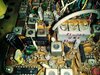
The UHIC chip - note the discoloration at the base leads going into the board - looks like something is going on reactively to the leads. See Pink Arrow.

You're getting lower MHz readings - you supposed to get a free running 35MHz + so you 3MHz low usually this means other problems too...

Note the Orange arrow pointing the your L19 - may mean an internal cap failed - so you know. Nothing serious but for best "Hints from HELLEN" - turn the slug in two turns and try a retune around it. IF the Frequency won't raise up or even get close to 35MHz free running (you may or may not get lock on this) - if you don't get anywhere - remove the coil and check the slug problem - you may have one in that one too.

Yellow Circle and Arrow, you have the "glue" that others have discussed as possibly reactive - which if you try to unsolder this - be gentle - it's not welded on there - those components are soldered to a simple board internally.

CobraRadioLEAPFROG.jpg
 
1977 date code on the MB8719 PLL chip.

Might be more than just one issue in a 1978 or 1979 radio.

Never learned to troubleshoot a PLL without a 'scope.

Seeing 10.24 MHz on pins 7 and 8 is where I would start, followed by pin 17.

Those are the two input signals the chip depends upon.

73
 
  • Like
Reactions: Handy Andy
teaberry_stalker_ix_xv_sm_sch_pg33.jpg
 

Attachments

  • Like
Reactions: Handy Andy

dxChat
Help Users
  • No one is chatting at the moment.