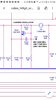
Kaos, the guys are giving you good advice, and just because you don't see a TP14 silkscreened on the PC board does not mean that it's not pin 7 of IC3.
ALL 148GTL radios use this test point regardless of where or when they were made.
heck, all MB8719 PLL chip SSB radios use this test point to align the IF offsets.
so, if you want to do the alignment the way the manual says, then hook your probe to pin 7 of IC3 and follow the alignment instructions.
HOWEVER!!!
If you have spent much time around these radios, you will have undoubtedly noticed that the signal level at this point is VERY low, and it can be a real PITA to get a solid reading on your freq. counter on SSB.
Some freq counters are sensitive enough to pick this signal up, and of course those are the more expensive "lab quality" instruments.
This is exactly why sonoma and Robb are talking about using the "1Khz tone" method.
This method works great every time you do it, as long as you know that the tone you are using is exactly 1000Hz. (i used to use a youtube video for this before i got a tone gen.)
Robb mentions using an RF sampler with the radio going into a dummy load, but just in case you don't have an RF sampler yet; there is another similar method.
all you have to do is remove the wires from TP7 and TP8. these are your bias test points for the driver and final, and without the wires connected, they won't amplify.
because of this, the level of output is so low that it won't even register on a wattmeter, but it is still plenty strong enough to be picked up by your freq counter.
this means that you can just connect your counter probe to the antenna jack center pin, and the negative lead to the chassis of the radio.
You will notice that if you do the AM adjustment first, you are already set up for the SSB adjustments.
make sure the clarifier is centered, align the VCO portion of the radio (34.xxxmhz), then move on to the offsets. do the AM one first, then turn the mic gain up, hold your mic up to a speaker with a 1khz tone coming out of it, and read the frequency on your freq. counter.
think about it this way: channel 20 is 27.2050 mhz. add 1khz to this and you get 27.2060 mhz (this will be your USB measurement)
subtract 1khz from it and you get 27.2040 mhz (LSB).
this method is tried and true and works great.
i did want to add though since you just got a new freq counter to be careful.
we all get the same feeling when we get our first freq counter, and that is that we can finally get our radios right on freq. so we jump right in and set them all perfectly with our used freq counter which is just a bit off freq.
now we have adjusted all our radios off freq. by that amount.
not sure if you've calibrated that counter yet, but you ABSOLUTELY need to before you start turning screws.
good luck!
LC