I'm building a 2 element yagi with a direct fed isolated split driven element. I would like to feed it with a Hairpin match and a 1:1 current choke. All the hairpins I have seen are on a beam of 3 or more elements with the hairpin rods facing the director elements. Can the Hairpin rods face the reflector on a 2 element flat side yagi with no issues??

You are using an out of date browser. It may not display this or other websites correctly.
You should upgrade or use an alternative browser.
You should upgrade or use an alternative browser.
-
You can now help support WorldwideDX when you shop on Amazon at no additional cost to you! Simply follow this Shop on Amazon link first and a portion of any purchase is sent to WorldwideDX to help with site costs.
-
A Winner has been chosen for the 2026 July 4th Retevis RA89R Giveaway! Click Here to see who won!
2 element Yagi with a Hairpin match
- Thread starter Lomchivok
- Start date
Makes no difference which way it is pointed. this is my hairpin match aka Beta match on my home made six element 6m yagi. The reflector is to the left and the directors to the right. Grounding the middle still preserves the balance and also grounds the antenna which would otherwise not be. 

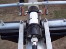

One of the reasons you may only see a Beta match on a mulit-element yagi mis that the Beta match is meant to match really low feedpoint impedances A multi-element yagi will generally have a much lower feedpoint impedance than a simple two element, IOW your Beta match may not work with a two element. Try it see I guess.
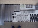
Well, I built the hairpin last night. Building the 1:1 choke today. I've got most of the hardware and all the elements to complete it. Gotta find a 2" aluminum boom. From the get go this project has turned from just a rotatable dipole to a 2 element with the expectations of turning it into a 3 element later if the 2 element doesn't work out. This beam is being constructed from a 4 element HF yagi with 1" radials and a mangled hairpin that hit the deck. All the elements were tweaked a bit but not broken and straightened out by spinning them in a long bed lathe. Probably should just finish it off as a 3 element, but what's the fun in that.One of the reasons you may only see a Beta match on a mulit-element yagi mis that the Beta match is meant to match really low feedpoint impedances A multi-element yagi will generally have a much lower feedpoint impedance than a simple two element, IOW your Beta match may not work with a two element. Try it see I guess.
BTW the driver element must be shortened from the "standard" formula for a half wave element if you are using a Beta match. As mentioned the feedpoint impedance must be lower than the coax impedance which is standard at 50 ohms. The Beta match is useable to about 35 ohms and preferably 25 ohms or less. I don't think you will achieve those parameters with a simple two element unless you use VERY close spacing but that adds other problems with gain and F/B ratio. My 6m yagi is six elements and OWL design.......Optimised Wideband Array and I use a 4:1 coaxial balun. Driver impedance is close to 12 ohms and I get a perfect match using it. Here is a link to some good info. http://on5au.be/content/a10/trans/beta.html
As an example of what I did check out these dimensions but keep in mind this is for 6m aka 50 MHz but notice the close spacing of the driver and the first director. This, along with the additional elements, lowers the feedpoint impedance considerably making the Beta match ideal for use with it. Dimensions on the left are in inches and are element spacing while dimensions on the right are for element lengths.

As an example of what I did check out these dimensions but keep in mind this is for 6m aka 50 MHz but notice the close spacing of the driver and the first director. This, along with the additional elements, lowers the feedpoint impedance considerably making the Beta match ideal for use with it. Dimensions on the left are in inches and are element spacing while dimensions on the right are for element lengths.
Welp, the hairpin didn't work, well it did with shortening the boom length but that did create different issues as mentioned above. I ended up just playing with the boom length at around .225 wavelength then the driven and reflector element lengths. Worked out pretty well with 1.09:1 swr and very good R and X. Ha, first contact I made with it was to 14 India Radio 224 France with a 5X6 signal report. Pretty happy with it so far, just wish it had more back side rejection but it is working like a 2 element should.

I've been wondering this for a while but I haven't got around to making my 2 element yet. I was planning to hairpin match it too, but I never thought of there not being a low enough impedance to do it until reading this thread. Did you measure the feed point impedance with the original boom dimensions? If you can shorten the driven element enough to make the feed point conductance cross the 0.02 S line, you can hairpin match it to 50+j0.Welp, the hairpin didn't work, well it did with shortening the boom length but that did create different issues as mentioned above. I ended up just playing with the boom length at around .225 wavelength then the driven and reflector element lengths. Worked out pretty well with 1.09:1 swr and very good R and X. Ha, first contact I made with it was to 14 India Radio 224 France with a 5X6 signal report. Pretty happy with it so far, just wish it had more back side rejection but it is working like a 2 element should.
I used to build 2 element 11m yagis using a delta match to a 4:1 transformer at the coax connector. Once I began experimenting with the Moxon antenna I never built another 2 element yagi.
Last edited:
I'd have to agree. Moxon's just seem to naturally go to 50 ohms with a bonus of closing the back door receive and transmit pretty hard at resonance. The gain is nice and the large front lobe makes aiming pretty easy.I used to build 2 element 11m yagis using a delta match to a 4:1 transformer at the coax connector. Once I began experimenting with the Moxon antenna I never built another 2 element yagi.
Hey mate, do you have the measurements. I had the same on my 6m yagi, but trying remember where I got the details, believe it was an ARRL book, but can't seem to put my finger on it.Makes no difference which way it is pointed. this is my hairpin match aka Beta match on my home made six element 6m yagi. The reflector is to the left and the directors to the right. Grounding the middle still preserves the balance and also grounds the antenna which would otherwise not be. View attachment 58205
Cheers
Robert
Hey mate, do you have the measurements. I had the same on my 6m yagi, but trying remember where I got the details, believe it was an ARRL book, but can't seem to put my finger on it.
Cheers
Robert
All I can tell you is it is about 8 or 9 inches long and about 2 inches wide. Sorry.
Simple answer, yes, you can use a hairpin.I'm building a 2 element yagi with a direct fed isolated split driven element. I would like to feed it with a Hairpin match and a 1:1 current choke. All the hairpins I have seen are on a beam of 3 or more elements with the hairpin rods facing the director elements. Can the Hairpin rods face the reflector on a 2 element flat side yagi with no issues??
To find out, I modeled a dipole alone at 20' in the air over real ground and got this:

Now to add the parasitic element. For this, I chose to go with a director instead of a reflector, because if you only have two elements total, you only get a tiny improvement in gain with the reflector over a director, but using the director, the spacing is much smaller. So, here we have a driven with a single director (no reflector).

The feed point impedance dropped as expected (as it would have with the reflector too). This is what happens if we do our best at matching with just a hairpin. In this case, the hairpin must have an inductance of 620nH

but if we also use a series capacitor, you can land it right on 50Ω and the values become 430nH and 560pF

The bottom line is that none of these numbers really matter, as you will probably use a different height, have different ground conductivity etc. This is where a nanoVNA or another antenna analyzer is worth its weight in gold. You can end all matching problems just by putting in your known feed point impedance and correct for that perfectly.
Hairpins are simply shorted stubs, and just like the coax equivalent, they are inductive under 1/4λ. The first step is to find the characteristic impedance of the open wire transmission line the hairpin is made of Zo = 276 * log(2s/d) where s is wire spacing center to center and d is diameter of wire (in same units). Then, to know the inductive reactance of the stub, you just multiply that by the tangent of its length in degrees.
Here is an example. Lets rearrange that and solve for the 430nH hairpin.
Find inductive reactance of 430nH:
Xl = 2*pi*27200000*.000000430 = 73.5Ω
Next, we need to decide on some dimensions for the hairpin, lets say 1.9" spacing with a wire diameter of .15". Lets figure out the characteristic impedance of a line of those dimensions:
Xo = 276 * log (2*1.9*.15) = 387.4Ω
The final question is at what length will the stub exhibit the necessary 106Ω?
invtan(73.5Ω / 387.4Ω) = 10.7°
The VF in air is 299705000m/s so 1λ at 27.2MHz is 433.8"
433.8" * 10.7°/360° = 12.9" is the hairpin length
With that out of the way, you can probably see why it is beneficial to try to adjust the antenna so the complex impedance lands on that .02s constant conductance curve, because if it were there, the hairpin would get you to 50Ω without other components like that capacitor in pic 4

I know this reply is way too late as the OP got it working, but I figured details on the hairpin calculations might be useful info to someone..
Last edited:
Thanks for the reply, very interesting. I am considering to convert it to a director rather than a reflector. Its kinda disappointing while pointed and talking to Australia (west) at 9 s units that folks in Wisconsin (east) can hear me at 7. The back end of this thing is nearly wide open...excellent side rejection. It is useful though for local coms, I can talk to both north and south locals off the front and back easily.Simple answer, yes, you can use a hairpin.
To find out, I modeled a dipole alone at 20' in the air over real ground and got this:
View attachment 66323
Now to add the parasitic element. For this, I chose to go with a director instead of a reflector, because if you only have two elements total, you only get a tiny improvement in gain with the reflector over a director, but using the director, the spacing is much smaller. So, here we have a driven with a single director (no reflector).
View attachment 66324
The feed point impedance dropped as expected (as it would have with the reflector too). This is what happens if we do our best at matching with just a hairpin. In this case, the hairpin must have an inductance of 620nH
View attachment 66325
but if we also use a series capacitor, you can land it right on 50Ω and the values become 430nH and 560pF
View attachment 66326
The bottom line is that none of these numbers really matter, as you will probably use a different height, have different ground conductivity etc. This is where a nanoVNA or another antenna analyzer is worth its weight in gold. You can end all matching problems just by putting in your known feed point impedance and correct for that perfectly.
Hairpins are simply shorted stubs, and just like the coax equivalent, they are inductive under 1/4λ. The first step is to find the characteristic impedance of the open wire transmission line the hairpin is made of Zo = 276 * log(2s/d) where s is wire spacing center to center and d is diameter of wire (in same units). Then, to know the inductive reactance of the stub, you just multiply that by the tangent of its length in degrees.
Here is an example. Lets rearrange that and solve for the 430nH hairpin.
Find inductive reactance of 430nH:
Xl = 2*pi*27200000*.000000430 = 73.5Ω
Next, we need to decide on some dimensions for the hairpin, lets say 1.9" spacing with a wire diameter of .15". Lets figure out the characteristic impedance of a line of those dimensions:
Xo = 276 * log (2*1.9*.15) = 387.4Ω
The final question is at what length will the stub exhibit the necessary 106Ω?
invtan(73.5Ω / 387.4Ω) = 10.7°
The VF in air is 299705000m/s so 1λ at 27.2MHz is 433.8"
433.8" * 10.7°/360° = 12.9" is the hairpin length
With that out of the way, you can probably see why it is beneficial to try to adjust the antenna so the complex impedance lands on that .02s constant conductance curve, because if it were there, the hairpin would get you to 50Ω without other components like that capacitor in pic 4
View attachment 66327
I know this reply is way too late as the OP got it working, but I figured details on the hairpin calculations might be useful info to someone..
dxChat
- No one is chatting at the moment.