yes, the guy down the road brought me a JB-12
"Receive Boost Amplifier" (cute, ha ha) to repair a few months ago.
as Nomad said, the negative bias. pull that 6BQ5 out,
don't let it get red. no need for it to be in the circuit at this
point. power up and measure around negative 45
volts at tube socket pin 2, the control grid. if it's not there,
go back to the power supply and check. trace it through the circuit.
maybe the relay contact. ?? diodes, filter cap, that adjustable coil.
But sounds like your plate and screen voltages are good, if it's
getting red hot.
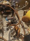
the JB-12 I had was worked on by someone, and they messed it up.
incorrect wiring, bad soldering. . and of course "R" and "T" are
interchanged in real life, since it is not a "Receive Boost Amplifier"

 does anybody have any other ideas? Thanks