Looks good. A few extra capacitors paralleled here and there will greatly improve your amplifier at 50MHz.

You are using an out of date browser. It may not display this or other websites correctly.
You should upgrade or use an alternative browser.
You should upgrade or use an alternative browser.
-
You can now help support WorldwideDX when you shop on Amazon at no additional cost to you! Simply follow this Shop on Amazon link first and a portion of any purchase is sent to WorldwideDX to help with site costs.
-
A Winner has been chosen for the 2026 July 4th Retevis RA89R Giveaway! Click Here to see who won!
6m Larcan Conversion
- Thread starter avistar23
- Start date
Looks good. A few extra capacitors paralleled here and there will greatly improve your amplifier at 50MHz.
I still need to drop by and see you about that.
 Perhaps next Saturday??
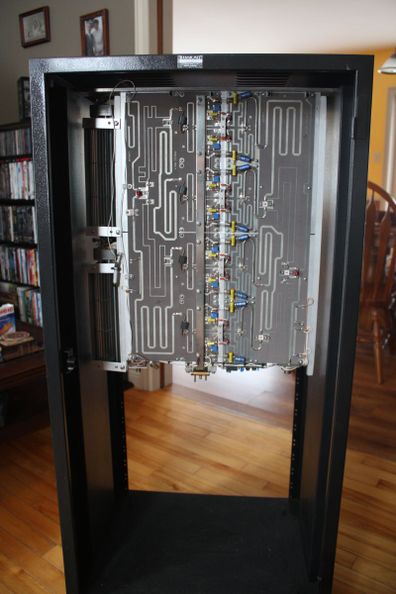
Mounted the amp module in the cabinet today as a trial run. First image is from the front with the blank panels removed. The fans are on the right. I thought they would be fine running in series with about 60 volts AC on each, which are rated for 100 volts each which is odd, but the air flow is not that great now that they are mounted in place. They must be Japanese fans. I have no idea where I got them and Japan uses only 100 volts AC for normal household voltage. I may have to wire them in parallel and use a dropping resistor.

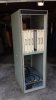
This is the view from the back with the door removed. I thought it would be easier to service from the back as there is total access without removing a bunch of front panels, just open the door and there it is.
Next weekend could work. Bring the module along and solder them in place too. We can run a few before and after tests.
That might work. Does it matter Sat or Sun.? The wife's last day off is Saturday and Sunday is clear. Just not sure if she wants to do anything on Saturday.
Evenings or weekends are often ok. I'm down with something nasty and keeping isolated from everyone for a few days. Otherwise give me a call and stop by.
Well........um........er.........ahhhhh...........let's make it next weekend instead. April 5 or 6.
That looks just like the one in the email I got. LOL Looks good.........too good. The only way it would look better is if it was in MY shack instead. 
BFLA? Big F'n Larcan Amp? :laugh:
BFLA? Big F'n Larcan Amp? :laugh:
Well I had the opportunity to go over to Warren's place (VO1KS) on Sunday to have some mods done to my Larcan amplifier module in an effort to increase the efficiency and lower the drive requirements on 6m. Basically it involved installing several SMD type capacitors on the input splitters as well as the output combiners.
Extra caps added to the main output combiner out to antenna.
Extra caps added to the combiners that combine two output modules into one that then feeds the main combiner in the first image.
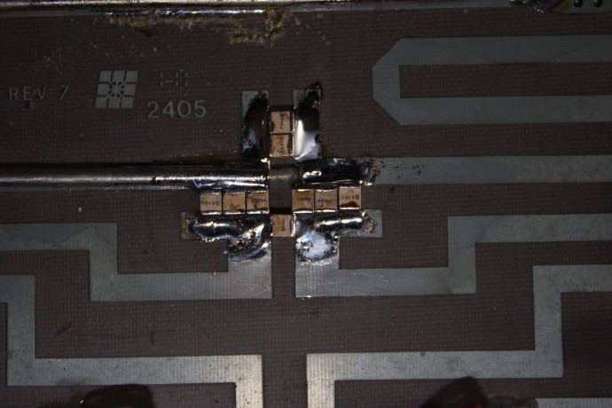
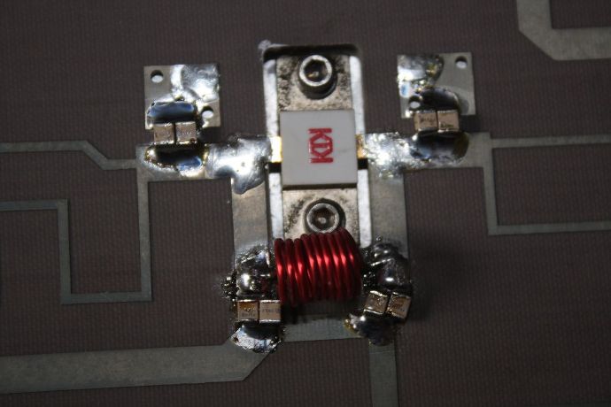
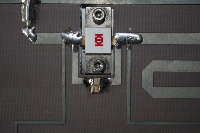
Several more caps added on the output of each of the four MRF-151G MOSFETS.
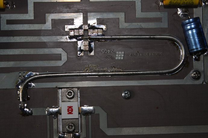
The long trombone shaped object is not a wire. It is a piece of semi-rigid coax cable that is used as part of the tuned circuit on the outputs of the FET's. One piece had to be replaced as I had a little accident that was not noticed until we got on Warren's work bench. The cable was pinched to the point of actually shorting it out.
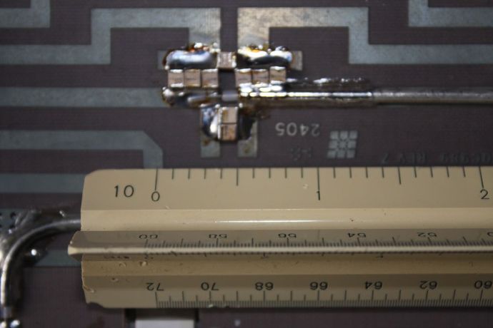
In case you are wondering what kind of size we are dealing with here is a picture with my scale showing the size of the caps and the coax cable. each division is 1/10 of an inch. The caps are basically 1/10 inch square.
When we started we had 5 watts of drive and 500 watts out with 38 amps at 50 volts. When we were finished we had 5 watts of drive yielding over 700 watts output and with just 7 watts drive we had a full 1 Kw output with the same 38 amps at 50 volts. The overall efficiency when we started was a dismal 27% but a respectable 50% when we finished which is about all that can be expected without a huge amount of more work and then the increase would only be minimal. Being clean class ab 50% is perfectly acceptable.I may be QRO on 6m this summer after all!
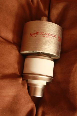
Speaking of QRO, Warren remember the question you asked me standing in the doorway of your garage? The question about the tube? Look what I found in my shop while looking for other goodies. I found another one that had a removal date on it (I forget when) and the notation. "Still makes 1.7 Kw". It was used in the QEI-3500 watt tx in Weymouth. That tx was limited to 2500 watts at the factory to increase it's efficiency at that power which is where it was normally run. I thought hmmmmm when I found it. When I pulled this one out I though holy crap! IT's NEW!!! Then reality sat in as there is no way i would have a new one but only maybe a pull or two. It does look super clean and shows no inter electrode shorts as far as I can see with just an ohmmeter. The ceramic as well as the silver plate looks REALLY nice and clean. Too bad I didn't have a test jig. LOL. I may have to speak to you again regarding a socket.
Extra caps added to the main output combiner out to antenna.
Extra caps added to the combiners that combine two output modules into one that then feeds the main combiner in the first image.
Several more caps added on the output of each of the four MRF-151G MOSFETS.
The long trombone shaped object is not a wire. It is a piece of semi-rigid coax cable that is used as part of the tuned circuit on the outputs of the FET's. One piece had to be replaced as I had a little accident that was not noticed until we got on Warren's work bench. The cable was pinched to the point of actually shorting it out.
In case you are wondering what kind of size we are dealing with here is a picture with my scale showing the size of the caps and the coax cable. each division is 1/10 of an inch. The caps are basically 1/10 inch square.
When we started we had 5 watts of drive and 500 watts out with 38 amps at 50 volts. When we were finished we had 5 watts of drive yielding over 700 watts output and with just 7 watts drive we had a full 1 Kw output with the same 38 amps at 50 volts. The overall efficiency when we started was a dismal 27% but a respectable 50% when we finished which is about all that can be expected without a huge amount of more work and then the increase would only be minimal. Being clean class ab 50% is perfectly acceptable.I may be QRO on 6m this summer after all!
Speaking of QRO, Warren remember the question you asked me standing in the doorway of your garage? The question about the tube? Look what I found in my shop while looking for other goodies. I found another one that had a removal date on it (I forget when) and the notation. "Still makes 1.7 Kw". It was used in the QEI-3500 watt tx in Weymouth. That tx was limited to 2500 watts at the factory to increase it's efficiency at that power which is where it was normally run. I thought hmmmmm when I found it. When I pulled this one out I though holy crap! IT's NEW!!! Then reality sat in as there is no way i would have a new one but only maybe a pull or two. It does look super clean and shows no inter electrode shorts as far as I can see with just an ohmmeter. The ceramic as well as the silver plate looks REALLY nice and clean. Too bad I didn't have a test jig. LOL. I may have to speak to you again regarding a socket.
Last edited:
Without that piece of coax being replaced the MRF151G would have made tiny crackles and died. I know the sound well now. Expensive oops sometimes and takes a bite out of my spare parts bin.
The soldering on the capacitors doesn't look as pretty when you take a macro picture and expand it on the screen! We should have taken a pic of the dented coaxial cable before it came off. Now I have to rebuild my dual band 6M/2M 250W amp after scavenging parts for yours!
There was a box of 3CX3000A7 socket rebuild parts on the dining room table. There should be at least 3 full sockets in the garage as well as several pulled tubes, two filament transformers, and a bunch of HV capacitors, rectifiers, etc for the power supply.
Without that piece of coax being replaced the MRF151G would have made tiny crackles and died. I know the sound well now. Expensive oops sometimes and takes a bite out of my spare parts bin.
It's called hazards of the job. LOL
The soldering on the capacitors doesn't look as pretty when you take a macro picture and expand it on the screen! We should have taken a pic of the dented coaxial cable before it came off. Now I have to rebuild my dual band 6M/2M 250W amp after scavenging parts for yours!
Now you are making me feel bad man.
There was a box of 3CX3000A7 socket rebuild parts on the dining room table. There should be at least 3 full sockets in the garage as well as several pulled tubes, two filament transformers, and a bunch of HV capacitors, rectifiers, etc for the power supply.
That kind of talk gets me all tingly feeling and it's not from the HV.
 Like I said, we may have to have a chat about that. I have yet again changed my plans for the Larcan amp.....I think. It may not go into that rack cabinet after giving the 3CX3000A7 another thought. I have an idea for now but need to take some measurements and figure a few things out first. That rack cabinet would be PERFECT for a 3CX3000A7 multi-band amp. I even have a pair (or three) of 10 Kv Jennings vacuum variable capacitors for the tune/load. The only thing is they are 1000 pF I believe which may serve fine as the TUNE but a little light for the LOAD on 80/160m perhaps.
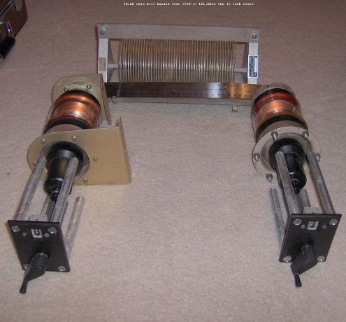
Or perhaps this 2000 pF bread slicer for the LOAD control.
I see online where one fellow was using a 3CX3000A7 in grounded grid and was getting 1500 watts out with 100 watts drive. A tube should last virtually forever with that kind of operation. GG is easy to implement and has only filament and plate supply but tends not to be the easiest to drive nor have the best IMD performance however...........
The guilt trip works. ")
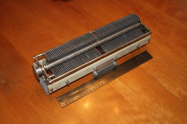
That's a nice output circuit. I didn't know you the roller inductors yet! I too had big plans for an HF amplifier until getting into my new house. There just isn't room to go big with the BFLA in there. With a different rack maybe a SB220 could be added, but with the IC2KL there isn't much point to go back to hollow state.
That's a nice output circuit. I didn't know you the roller inductors yet! I too had big plans for an HF amplifier until getting into my new house. There just isn't room to go big with the BFLA in there. With a different rack maybe a SB220 could be added, but with the IC2KL there isn't much point to go back to hollow state.
Sadly that is not a roller inductor. It is a Gates regular inductor out of a phaser unit that was at the old CKEN 1 Kw AM site I think. I have a couple such units each one slightly different.
I've posted the capacitor values that were added to improve 50MHz operation to the lo/lo amplifier.
Larcan 1kW and 1.5kW amplifier modules
144MHz conversion troubles with a new batch of capacitors. It seems the 100pF caps need to be about 105pF for proper operation. Many supplied measure in the low 90s and output power is considerably reduced. I have to go through the 150pF caps next and get the amplifiers operating at 1kW out.
dxChat
- No one is chatting at the moment.