
You are using an out of date browser. It may not display this or other websites correctly.
You should upgrade or use an alternative browser.
You should upgrade or use an alternative browser.
-
You can now help support WorldwideDX when you shop on Amazon at no additional cost to you! Simply follow this Shop on Amazon link first and a portion of any purchase is sent to WorldwideDX to help with site costs.
-
A Winner has been chosen for the 2026 July 4th Retevis RA89R Giveaway! Click Here to see who won!
6m Larcan Conversion
- Thread starter avistar23
- Start date
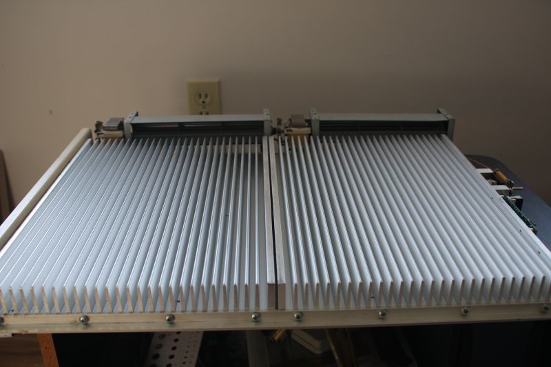
I took another look at what I have to stuff into the cabinet and how to do it today.The module I had mentioned about eventually using on 2m is in fact a 600 watt unit and not a 1.2 Kw unit as I had thought. It will need modifications to make it achieve anything near that and that will wait. The main effort is on the 6m unit. Since the 2m module was in fact originally a driver module the other half of the module consisted of an identical heatsink with just a splitter board mounted on it. I removed the splitter board and separated the unused heatsink from the module. This gives me two massive heatsinks now as some time ago I returned one of the VHF Hi band modules to Warren as he was in need of some parts but I was able to keep the unused heatsink.These measure 1.5 by 10.0 by 15 inches and weigh 13 lbs. each. Lots of cooling ability. This had me thinking about a nice high power dry dummy load using a pair of 800 watt 100 ohm ceramic chip resistors that are ideal for this purpose. Then it hit me....why not see how this project works out and if it goes well perhaps a fully homebrew kilowatt plus HF amplifier using the Freescale LDMOS devices on the market? 
I took a few measurements and was going to cut the 1.5 by 4 inch aluminum channel stock that will support the modules inside the cabinet however the thought of working with a table saw in an unheated workshop at -11C or about 12F was not that appealing. Warmer weather is on the way.........sometime.........I hope.
Back to work tomorrow so nothing but thinking about things for the next few days however if it warms up on Saturday I may get the brackets cut and trimmed to fit.
Garth: The high band gain curves are on my Larcan page. It drops very fast below 174MHz to about 10dB at 144MHz. I don't like to put more than 25W drive into the converted 2M Larcan with 16dB gain, so would not expect your high band amp to work well there. I've heard of no one using the high band for anything other than 222MHz. Your dreams of 600W on 2-meters is unlikley.
Mount your dummy load resistors on one of the unused heatsinks! 800W 100ohm resistors could be ideal for my 2M Wilkinson combiner. Do they use two terminals, both isolated from the mount? If there are two I'm very interested in getting at least one of them.
Mike: Lots of guys are using the lo/lo at 50MHz with no major issues. I had spare parts left from 2M conversions so figured it was worth messing with. Check the curves for lo/lo gain response. It drops fairly quickly below 54MHz. I measured drive power vs output power. With a few capacitors the gain improved considerably. I'll get the figures at home from my scribble pad. I try to avoid more than 40A @ 50V through the modules, and chose 10W as maximum drive level. I popped a FET with about 5W drive at 45MHz. They may be delicate if not tuned properly. The original amp will produce 1kW with 5W drive at 60MHz, but only about 600W at 50MHz. I'm now getting full power out at 50MHz with about 6W drive power. Didn't turn the input wattmeter element to measure reflected power.
I have a small cup of ceramic capacitors that were removed from the modules. Everything is tossed in together, nothing sorted. The values are not identical to what Dave suggested, but seemed close enough to make an improvement. Everything is tossed in together so it will take some sorting time to find the right components. It takes several lo/lo conversions to 144MHz to get enough parts for a single lo/lo improvement on 50MHz.
Just at work so can't elaborate but my idea for 600 watts on 2m from the Hi band unit was based on my thinking it was a full kilowatt unit so I would expect no more than half that from the driver unit I have. Still thinking about the HF LDMOS amp.
The input and output couplers are rated at 400W CW. With 25W max drive power and 10dB gain, I wouldn't expect the high band driver to be good for anything more than 250W. Even then, the tuning is so far off that you may pop one of the FETs while trying.
Any interest in getting on 222MHz? I want to assemble a pair of 1.5kW modules in parallel for up to 3kW output.
Any interest in getting on 222MHz? I want to assemble a pair of 1.5kW modules in parallel for up to 3kW output.
Understood aboit the Hi band unit. As for 222 MHz.....not much interest at all really. Just nothing going on here except maybe EME and MS. I would be more interested in 70 cm maybe as at least there is some terrestrial activity both local and tropo as well as EME and MS.
I'd like to get the UHF amps here working too, but they won't fit in the same module assembly with the Larcans.
Checked the 6-meter amp. 6.5W drive to produce 1kW output power. Reflected power about 150mW. Not great, but acceptable for ham radio use.
Checked the 6-meter amp. 6.5W drive to produce 1kW output power. Reflected power about 150mW. Not great, but acceptable for ham radio use.
That's about 1.35:1 for SWR. Not bad really but I agree it would be nice to see a perfect match. Any padding on tbat input? An attenuator may make that appear a little better. I plan to use a Henry (or maybe it was Florida RF Labs) ceramic chip attenuator rated for 100 watts and 10dB attenuation between my 100 watt exciter and the amp. That may make the input SWR a little better what do you think?
What was the match like before you modified the input/output tuning? I may have to take you up on your off to drop by with a magnifying glass. I may use a jewelers loupe instead. LOL
What was the match like before you modified the input/output tuning? I may have to take you up on your off to drop by with a magnifying glass. I may use a jewelers loupe instead. LOL
I didn't measure the input match before adding parts. It's easy to plug in another module to check. There are another 10-15 that have not been modified.
The 10dB pad should improve the match considerably. Return loss is about 16dB now, so the pad would improve it to 36dB which is about 1.1:1 swr. That assumes the pad presents a perfect match of course.
The 10dB pad should improve the match considerably. Return loss is about 16dB now, so the pad would improve it to 36dB which is about 1.1:1 swr. That assumes the pad presents a perfect match of course.


4kW 2-meter amplifier
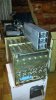
Someone asked if I could build a 4kW output amplifier for 2-meters. Not sure why, but Mr.Franklin speaks l loudly. Here is an initial suggested layout for the amplifiers. Four 1kW modules will operate in parallel. Four power supplies (3 shown) will mount in the two empty slots to the left. Input and output combiners are easily fabricated with 50 ohm cables. I don't know of any reasonably priced coaxial switches that will handle more than 1kW. The RF switching will be done at each amplifier input and output, leaving the 4-way splitter and combiner in circuit during receive also.
It could also be configured to work at 50MHz or 222MHz by changing the splitter/combiner.
The picture shows a 6-module enclosure that I plan to use for my personal station. Two modules in parallel per band will make it a tri band amplifier. Six power supplies will mount lower in the rack.
Attachments
4 Kw on 2m? :blink: Tell him he could do more with less if he used a long boom yagi instead of a 1/4 wave groundplane. 
I installed my attenuator last week and mounted the fans. I had a small panic moment when I was doing it however. I had it sitting on its edge on the small wheeled television stand I use for doing some work. I turned away for a second and it toppled over onto the floor. When I picked it back up I could see that the side rails were bent right between the heat sinks. I straightened that out and everything looks OK now but I was ready to drop a load at the time. The PC boards were flexed just enough to press against the heat sink. All is good now however.......I hope.
Got off work yesterday morning and spent the day chilling out during the storm. Today is clean up day after the yard is plowed. Might take a little drive to see how much snow has drifted around a little later. I don't go back to work until Sunday so I hope to get the module mounted in the cabinet and perhaps the power supply mounted as well.
I got my 100 ohm 800 watt resistors from Henry Radio the other day so I may start to throw together the 1500 watt dry dummy load together too.
Last edited:
Post a picture of your mounted attenuator. I have spare side rails if you'd like a set.
He's in an apartment complex and can't build a large antenna. Mr.Franklin remember...
He's in an apartment complex and can't build a large antenna. Mr.Franklin remember...
OK. You asked for pictures so here they are. BTW I am fine about the side rails.Thanks anyway. Things straightened out fine.One edge of the heatsinks were jammed together and that stopped things from bending any further. Everything straightened out with a little well placed pressure.
100 watt 10 dB RF attenuator installed on the input to the amplifier just ahead of the splitter.
Twin squirrel cage fans rated at 100 volts AC each. Wired in series they provide a lot of airflow yet run very quite.
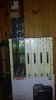
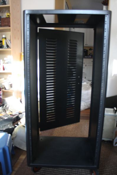
Back of the Hammond rack cabinet the amplifier and power supply will be installed in.
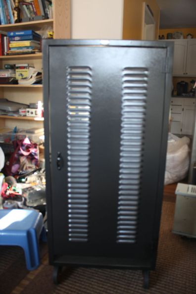
Front view of the rack cabinet. There will be a meter panel near the top indicating power supply voltage and current on separate meters and possibly an RF output meter as well if I can locate the nice little RF meter I seem to have misplaced. Blank panels will fill in the empty spaces.
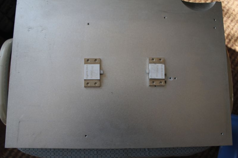
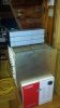
Pair of Florida RF Labs 100 ohm 800 watt ceramic chip resistors purchased from Henry Radio on Ebay to make a dry 1500 watt dummy load. The heatsink is one half of what is used on the Larcan amplifier module and measures 10 x 15 1/2 inches and will likely have a small fan depending how it handles the heat.
100 watt 10 dB RF attenuator installed on the input to the amplifier just ahead of the splitter.
Twin squirrel cage fans rated at 100 volts AC each. Wired in series they provide a lot of airflow yet run very quite.
Back of the Hammond rack cabinet the amplifier and power supply will be installed in.
Front view of the rack cabinet. There will be a meter panel near the top indicating power supply voltage and current on separate meters and possibly an RF output meter as well if I can locate the nice little RF meter I seem to have misplaced.
Blank panels will fill in the empty spaces.
Pair of Florida RF Labs 100 ohm 800 watt ceramic chip resistors purchased from Henry Radio on Ebay to make a dry 1500 watt dummy load. The heatsink is one half of what is used on the Larcan amplifier module and measures 10 x 15 1/2 inches and will likely have a small fan depending how it handles the heat.
dxChat
- No one is chatting at the moment.