• You can now help support WorldwideDX when you shop on Amazon at no additional cost to you! Simply follow this Shop on Amazon link first and a portion of any purchase is sent to WorldwideDX to help with site costs.

6m Larcan Conversion

Hi Warren. I was thinking of giving you a shout last week but things went rather badly when a co-worker suddenly died and that pretty much upset the week. It's been a while. Hope all is good. Sounds like you have been busy. I admit to being a bit lazy this past winter. Things are getting busy at work with nearly $15 million in new machines being installed. Lots of activity regarding them at work mostly just trying to prepare and move things to make room.

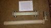
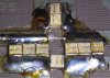
As for the amps, not much action as a result of the above. I just got into a rut and stayed there. Winter tends to do that to me. That hasn't stopped me from thinking and planning however. I have decided to just go ahead and get something on the air and fore-go a nice cabinet for now. Those amp modules are so long a standard rack cabinet is not deep enough unless you can get a deep unit but table-top deep units are hard to find. I think I will just make up a top and bottom panel for it and that will provide some extra shielding as well as allow better airflow along the length of the heatsink.The power supply can go under the desk nd the change-over relays can be attached to the rear of the amp. Since I currently have no antennas up for 6m,or any band really other than my doublet, the drive just hasn't been there.

That 2m conversion sounds good. I would think a kilowatt into a pair of stacked 13B2's at about 68 and 78 feet should work nice. If nothing else it should ensure a good signal into the Falmouth repeater from here. :D
 
hey, i also was going to contact you guys, i haven't made much progress either, i got caught up with a bunch of things and relocating my towers and re doing my antenna stuff, i also bought a boat which ended up taking up more time than i anticipated. im looking to order some good relays in the next week or so and finish up my 6m larcan, i would love to put one on 2m also, its hard for me to get the parts here for the conversion so ill be in touch.

Mike

C6ANU
 
I'm planning a tri band Larcan amplifier. Two parallel modules on each of 50MHz, 144MHz, and 222MHz. All six mount vertically in a modified Larcan frame. Output power 2kW per band, possibly in excess of 3kW when I find suitable 1.5kW modules.

I picked up a HP power supply frame to hold six of the 50V 3kW supplies. It will be limited to a 240VAC 30A circuit, so could not operate all three bands simultaneously at full power.

A picture of the 6-module wide frame is on bottom of my Larcan page.
Larcan 1kW and 1.5kW amplifier modules

I still need antennas. Hard to use the RF when it all goes to a dummy load.
 
I'm planning a tri band Larcan amplifier. Two parallel modules on each of 50MHz, 144MHz, and 222MHz. All six mount vertically in a modified Larcan frame. Output power 2kW per band, possibly in excess of 3kW when I find suitable 1.5kW modules.

:p
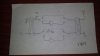
: :drool: How do you plan to combine the pairs Warren?

I picked up a HP power supply frame to hold six of the 50V 3kW supplies. It will be limited to a 240VAC 30A circuit, so could not operate all three bands simultaneously at full power.

A picture of the 6-module wide frame is on bottom of my Larcan page.
Larcan 1kW and 1.5kW amplifier modules
Interesting. Where would one acquire such a beast to house multiple power supplies? Cheaply might I add.

I still need antennas. Hard to use the RF when it all goes to a dummy load.
I hear ya on that one buddy. There are more efficient ways of heating the house. LOL.
 
This writeup by Dave Olean will improve the Lo/Lo performance at 50MHz. I used leftover parts scavenged from the 2M conversions to add to mine. Stop by with a magnifying glass and you can have a few capacitors Garth.

http://www.mmra.org/larcan/Improving the Larcan Amplifier at 50MHz.pdf

50MHz and 222MHz I have 3dB couplers rescued from the recyclers following transmitter decommissioning. RF switching is an issue. I don't know of any switches to handle 3kW. They will handle 1.5kW, so the 3dB couplers will remain inline on receive as well, and the switches bypass the amplifiers as needed. I'll take pics and post later.

144MHz is still being worked on. I may have to use a 75 ohm cable splitter at the input, and get a high power combiner from eBay.

144 MHz VHF Power Splitter Combiner Ham Radio Module 2 x 1 5KW in 3 KW Out | eBay


The power supply frames can be found on eBay. Paul N1RJX found one for $60 and brought it to me last week. It's empty so now I need to find extra supplies. The frame is wired for positive ground and 3-phase AC power. All easily changed. It's huge too, almost 30 inches deep!
 
Output combiners

Output combiners for 50MHz and 222MHz.
8.5x11 paper will give size reference.
Input dividers are considerably smaller.
The quick hand drawn diagram shows how the switches will handle 1.5kW each and then combine afterwards for 3kW. Divider and combiner remain inline during receive also. The adjustable sections are to get phasing correct.
 

Attachments

  • Diagram.jpg
    Diagram.jpg
    126.8 KB · Views: 214
  • OututCombiners.jpg
    OututCombiners.jpg
    152.4 KB · Views: 187
Sounds pretty impressive Warren. I dare say that there are very few full legal limit capable stations on HF much less on the VHF bands so you will be at the top of the heap when all is said and done. For the benefit of the Americans reading this the Canadian legal limit is 2250 watts pep on SSB.

I was looking the other night on Ebay and I believe I saw the same power supply frame as it was also 3 phase and would hold six 3 Kw supplies. Seriously looking at picking up a few more of those HP blade server supplies and a rack frame unit.I think I may assemble everything into a half rack I have that was going to be used for an HF tube amp in the future however with the introduction of high power LDMOS devices the idea of a pair of 3-500Z's is having less appeal all the time. The only issue is that the rack is not as deep as the Larcan module so it will stick out the back a bit. I may get it out of the shop later today and get it into the basement for some experimenting. With a power supply rack on the bottom and the Larcan module mounted near the top there is more than plenty of room for an HF amp to be mounted in the future. This could use a common power supply making metering simpler as well. I have the 50 volt and 50 amp meters.Only problem is if the rack unit is as deep as you say, 30 inches. I may just mount a few PSU's without a rack unit and save a little on depth.

As for the article by Dave Orlean, I will have top read it again, and likely again after that, as I just got off work this morning and have had no sleep. Things don't sink in too well at the moment. I was confused because he started off with modifying a Lo-Hi band unit (ch. 5 & 6) but I have the Lo-Lo band unit (ch.2-4) . It sounds like he was still advocating modifying the input splitter and output combiner on the Lo-Lo units. See.....I told you things sink in slow right now. All it will take is some sleep and things will be better tomorrow. LOL.

Gotta go for now. I have a rack to move into the house and Ebay to scour for parts and a couple errands to run. If I see an aurora display to the east sometime I guess I'll know that you are finally putting some RF into something other than a dummy load. :laugh:
 
I have no idea what legal limits are in terms of DC input or RF output power. Should look into it a bit more before turning things on. Having an amplifier capable of 3kW output is really no different than driving a car capable of 100mph on a 30mph road. Just because it is capable of much more does not mean it has to happen.

That's the correct power supply frame you saw. It's a good start, but needs work to be useful. There are no vents going vertically for air flow, so it will have to go at the bottom of the rack. I'm hoping to get a 30 inch deep rack with side panels. Everything should fit inside quite nicely. If there is enough room, the IC706 and IC-2KL amplifier could go in there too. Lots to expect from a 30A circuit.

Dave's improvement writeup essentially amounted to paralleling a few capacitors on the input splitter, PA output board, and the output combiner board. I used leftover parts removed from lo/lo modules during 2-meter conversion. The values weren't exact, but were close enough and there is a noticeable improvement. I think there are 20 components to add. The price was right. Free plus about 30 minutes soldering time.
 

Attachments

  • 6MOptimize.jpg
    6MOptimize.jpg
    253.7 KB · Views: 207
Good picture. It reminded me that the next time I am asked what I want for Father's day or my birthday (both in June) I should answer "One of those magnified inspection lamps on the swing arm." :blink: LOL

I wouldn't worry about the single 30A circuit. It's not like you will be transmitting on more than one band at any given instant. Power levels BTW are 2250 pep for any type of SSB emission which tecnically includes PSK, RTTY, etc. and 750 watts carrier for any type of carrier emission be it CW, FM, or AM. that one I have yet to figure out because 750 watts of AM carrier is 3000 watts pep at 100% modulation. Oh well, tis not mine to figure out but rather just follow and abide.

Uggghhh....just brought my rack cabinet in the house. It's not as deep as I had thought. It is only 16 inches deep with the rear door off and only about 15 deep with it on.

Sorry for the quality. I just used my phone as the camera is packed away in it's carry bag.

ra8a.jpg


I might be able to adapt it so it will look decent. The only thing is the amp sticking out the back. The power supplies can be mounted no problem as can everything else.
 
Photos

The swing arm magnifier won't do much for reading values from the capacitors. I take pictures using my cell phone and then magnify them to ensure values are correct. Go ahead and critique my soldering skills.

There seem to have been changes from the schematic diagram to what Larcan sent off the production line.

Could you mount the amplifier vertically with connectors top or bottom?

Mine have to slide in with connectors on back as that's the way Larcan decided. Not much other option for six modules and the power supply frame.
 

Attachments

  • Capacitors.jpg
    Capacitors.jpg
    216.2 KB · Views: 190
The swing arm magnifier won't do much for reading values from the capacitors. I take pictures using my cell phone and then magnify them to ensure values are correct.

I have a couple of cheap jeweler's loupes for checking tiny part numbers but the swing arm magnifier will come in handy for normal fine work. things are better with the new bifocals but nevertheless sometimes things just need to be a little bit bigger. :D

Go ahead and critique my soldering skills.

Nope. I have done some stuff I was proud of and others that I want to hide. Your's is somewhere in that range. (y)

Note to self: Dig out that 15 watt pencil iron with the super fine tip.

There seem to have been changes from the schematic diagram to what Larcan sent off the production line.

Just what every tech/equipment modifier wants to hear. :headbang

Could you mount the amplifier vertically with connectors top or bottom?

:blink: See,I told you earlier that things sunk in slow right now. Been up since 3:30pm yesterday and only five hours sleep at best since Friday morning with two twelve hour shifts thrown in there for good measure. That's a great idea and one I will have to look at hard. I have a couple rack shelves that can be installed to hang the module from if needed. THANKS for the idea! (y) I also have enough blank panels to fill the front (I think) so I am good in that regard.

Mine have to slide in with connectors on back as that's the way Larcan decided. Not much other option for six modules and the power supply frame.
 
Well I took another close look at the cabinet and amp module today. As of now the plan is to mount a piece of 1 3/4 by 5 inch aluminum channel stock across the top of the cabinet inside. Properly shaped this will have a flange that will rest on top of the two inner panels on either side of the rack. This will make a very strong point to mount the modules and hang them vertically. They will have the Larcan front panels removed and bolt to the channel stock. I will mount the modules back to back with the heatsinks together.This will allow component side access for one amp from the rear via the open door or for the other amp via removing blank rack panels from the front. This will also allow a common cooling fan system as it can flow across the two heatsinks at the same time.I have a pair of 100 volt longitudinal blowers that run very quiet when wired in series with 120 volts and still provide plenty of airflow.Note I speak in plural.One of the modules will of course be the Lo-Lo unit for 6m and the other is a Hi band unit that I will experiment with with the intentions of using it on 2m with whatever I can get out of it. I'll have to look at the input and output circulators as they are rated 160 MHz on the low end. Even if I just get 500 watts or so out it would be great. 500 watts into stacked 13B2's will do a little something. There is just enough room to mount the fans on the side of the amps and have the air blow from one side to the other. The cabinet is well vented on top, sides, and back. The power supply unit(s) will also be mounted vertically on either side of the cabinet.Starting to get serious about this now. Too bad i go back to work Friday.
 
would it be worth it for me to do the mods to the lo-lo? can i grab a few of those caps in the mail to do the conversion, will paypal you for it, i put up my 5 element medium boom antenna tonight in an effort to work fk8cp who has been emailing me non stop about getting fl15 on 6. i will order relays and hope to be on the air by the end of the month with my amp. my bird meter quit on me today, i dont know where the issue is. but my antenna system is perfectly flato n 50.110, all i need to do is add my amp to the mix.
 
Hi Micheal.Not sure how much of a difference the mods will make but Warren has said it is noticeable. It probably just causes a bit more gain that can likely be offset by higher drive levels if it is not done.

Boy,FK8CP hey? That would be an excellent contact for sure but just not too realistic during this stage of the cycle I don't think. Not for here anyway, maybe 6m propagation to the Pacific is better for you. I still don't have any antennas up yet and won't until summer so even if I had the amp working right now all I could do with it is heat the house. :laugh:
 
he claims hes been hitting the states and south Florida with guys only using a dipole, only time will tell, i havent gotten him or much of anything on 6 lately. i spoke to Dave about the mods months ago when i was buying an antenna from him and he made it sound like the internal match on 6 was horrible for the amp, but Warren disagreed, either way im going on the air soon, however my bird meter seems to have stopped working for no apparent reason this evening. have never had one with an issue so im not really sure what the problem is.
 

dxChat
Help Users
  • No one is chatting at the moment.