• You can now help support WorldwideDX when you shop on Amazon at no additional cost to you! Simply follow this Shop on Amazon link first and a portion of any purchase is sent to WorldwideDX to help with site costs.

858 Chassis Frequency Counter Internal hookup Recieve/Transmit

giboni

Break Break..Does anyone have any Grey Pupant ?
Sep 24, 2014
119
39
38
66
Nebraska
Maybe "399" might be kind enouph to impart his experience and knowledge !

I have seen them on Ebay. Just missed out again on another one. Robyn 520D with counter installed.

Couldn't afford to bid on it. Anyways I didn't like the way the Radio looked

Not the digiscan. Just a frequency counter.

Anyone know the step by step instructions /parts/ and offset to program the counter?

The location near the VCO it has to be connected to? I bought several $9.80Flea Bay shipped counters.

They work really well. Appear quite sensitive. I purchased the 6 digit ones. Not 8. Cheap though 12.49.

I have a Trc457 with digi Scan. But looking at that did not trigger my brain on how to connect a counter to my other 858 base stations 458/139/Pressident Washington/Madison.

Would really appreciate it !

I tried. Could not find anything on the Web, CB tricks Depfom, etc.

I know you can't load down the VCO. But obviously there is a way !

Recieve and Transmit. Not the 4 turns around the coax method.

Very helpful and beats looking at a chart.

Thanks.

73s John
 

Attachments

  • 520D.jpg
    520D.jpg
    355.7 KB · Views: 49

the counters you purchased, can you program an offset frequency in the counter?

you will need an offset for the counter to display the correct frequency
 
the counters you purchased, can you program an offset frequency in the counter?

you will need an offset for the counter to display the correct frequency


Yup. They can be set with offsets. They also require a case.

If you are going to have them external.

I used scraps of metal studs to make a quick case with Zippys. You can use tin Cans.

Need to know where to hook it up. Value of coupling capacitor/resistor.

Best John
 
Okay,

Looked at the FC 347 schematic on CB Tricks. It appears that I have to add 6 x 22K
resistors and two more leads to the cost effective FleaBay counter.

This will cover USB and LSB.

I found this Mod in an archive for installing an early version FC347 to a Cobra 139XLR.

http://www.voy.com/71084/6/2101.html

A 1/2 watt 9 volt zener off the PSB in the Radio to power the FleaBay counter.


Now I need to get shielded Coax. I think just order the 50 Ohm cable that is used to connect routers and antennas. Cheap for twenty feet. Need it anyway to do PLL Mods
properly. 2.99 shipped.

56Pf Capacitor. No problem. I get these PF values from a small pile of parts Radios.

Mostly Gallaxys that the local CB shop Gave me. A sillicon diode and possibly a 22k resistor,
after the 56PF and before the other two leads which have 7.2V when switched in.

Lets see if it works?
 
  • Like
Reactions: space cowboy
cobra 139 is the 858 chassis.

video cables, the type one would use to connect a dvd player to the tv works great

I put an female rca jack in the back of the radio and plug the freq counter into it instead of hard wiring into the chassis

if your freq counter has programmable offsets and more than one setting you can program the offset in for usb.lsb and am.

N3ZI freq counter kits work good for that.
 
Giboni -
If you are connecting the counter to an 858 SSB chassis, first set the counter to subtract an offset of 7.8 mhz. Then connect the counter input to GATE 1 of FET 4 (Same as pin 10 of UHIC005) through a 39pf capacitor. See Diagram below. Be sure to use an isolated tip soldering iron and a grounding bracelet, as these older FETs are easily damaged from static discharge.
The counter will now read out in TX and RX, and will track the clarifier. Good luck and 73s. BTW ... can you post a link to the place where you bought those counters??

- 399

858SSB counter hookup.png
 
Last edited:
hello everyone and blessed 73's i have a cobra 139 XLR cobra base with PC176AB chassis D858 pll, this radio has been tricked so i need to install this freq counter i bought from ebay 8-digit LED Frequency Counter Module
Model PLJ-8LED-C
so i need help with install of this unit102_1404.JPG 101_5231.JPG 102_1404.JPG 101_5231.JPG
 
Last edited:
Biggest problem you'll have with the '858 SSB radios and a FC390-type display will be in AM mode.

The PLL does a 1.5 kHz (I think) "jump" between transmit and receive modes when running AM.

Doesn't do this for sideband. Keying the mike won't make the display jump in SSB modes, only AM.

The three crystals in the PLL that each have a trimmer cap are not organized like all your later radios, where one trimmer cap is for each mode.

This radio uses one crystal for AM receive ONLY, the one positioned most-inboard is AM receive only. One of the SSB crystals gets selected for AM transmit. Can't remember which.

This means that your counter will "jump" a kiloHertz and a half when you key the mike on AM.

The only counter I have seen that gets around this problem came from Ralph at Backwoods RF. Uses the name fast*track09, I think on Ebay. His workaround is to count the input frequency to the PLL chip, and NOT the VCO signal that feeds into the transmit and receive mixers. That method is what you see in the Cobra 2000 and Galaxy radios.

The drawback of Ralph's method is that turning the clarifier has no effect on the displayed frequency. The PLL chip always gets fed the same frequency for the channel you are on, no matter where the clarifier is turned.

Still a clever solution, IMHO.

73
 
thanks for this input in fact it is ralph who i bought this freq counter from here is still my problem,
WHERE do i solder the connections at on the board ??? this is the freq counter i bought from ralph
8-digit LED Frequency Counter Module Model PLJ-8LED-C google it will come up with the manual if I knew ho to upload the pdf i would opps i figured how to upload hope this file helps

my radio is a cobra 139 xlr with PC176AB board with d858 UNIDEN PLL CHIP same as the robyn 520D (?)


Biggest problem you'll have with the '858 SSB radios and a FC390-type display will be in AM mode.

The PLL does a 1.5 kHz (I think) "jump" between transmit and receive modes when running AM.

Doesn't do this for sideband. Keying the mike won't make the display jump in SSB modes, only AM.

The three crystals in the PLL that each have a trimmer cap are not organized like all your later radios, where one trimmer cap is for each mode.

This radio uses one crystal for AM receive ONLY, the one positioned most-inboard is AM receive only. One of the SSB crystals gets selected for AM transmit. Can't remember which.

This means that your counter will "jump" a kiloHertz and a half when you key the mike on AM.

The only counter I have seen that gets around this problem came from Ralph at Backwoods RF. Uses the name fast*track09, I think on Ebay. His workaround is to count the input frequency to the PLL chip, and NOT the VCO signal that feeds into the transmit and receive mixers. That method is what you see in the Cobra 2000 and Galaxy radios.

The drawback of Ralph's method is that turning the clarifier has no effect on the displayed frequency. The PLL chip always gets fed the same frequency for the channel you are on, no matter where the clarifier is turned.

Still a clever solution, IMHO.

73
 

Attachments

  • PLJ-8LED_Manual_Translation_EN.pdf
    696.8 KB · Views: 56
Last edited:
LINK TO WHERE I BOUGHT THE FREQUENCY COUNTER
http://www.ebay.com/usr/fasttrack*09?_trksid=p2047675.l2559

Giboni -
If you are connecting the counter to an 858 SSB chassis, first set the counter to subtract an offset of 7.8 mhz. Then connect the counter input to GATE 1 of FET 4 (Same as pin 10 of UHIC005) through a 39pf capacitor. See Diagram below. Be sure to use an isolated tip soldering iron and a grounding bracelet, as these older FETs are easily damaged from static discharge.
The counter will now read out in TX and RX, and will track the clarifier. Good luck and 73s. BTW ... can you post a link to the place where you bought those counters??

- 399

View attachment 15285


Like this one?

https://www.circuitspecialists.com/21cb039.html


And where do you ground the counter? I assume ground the bracelet to the radio itself?
 
Last edited:
We discovered that the protection diodes on the input of the 6-digit version cause trouble if you simply connect the input directly to a radio like this.

We found that a suitable resistor worked better than a disc capacitor, and prevents the counter's input diodes from "loading" the radio's internal PLL output level. Causes receiver performance and transmit power to fall off when this happens.

The schematic labels "TP8" as the output of the radio's PLL feeding into the receiver and transmit mixers. This is one pin of L16. On one side of L16 there are three pins. On the other side there are only two. One is grounded. The other one of these two pins is TP8. I would start with a 470-ohm 1/4-Watt resistor between the counter's input wire and the tap-off point in the radio. If the counter's display is not stable, a lower resistance value may be called for.

Couldn't find a pic of TP8 on file here.

I do have one suggestion about PLJ counter displays. Don't power it directly from the radio's main power. We found the counter's on-board regulator will overheat if powered from more than about 10 Volts. We adopted the habit of installing a 8-Volt regulator to power these. The generic part number is "7808T".

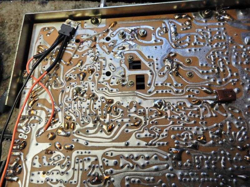
Here's where we installed one in a Cobra 139XLR.

EdyYGn.jpg


Soldering the regulator's metal tap to a decent-size ground foil will take care of the regulator's heat-sinking needs as a rule.

*** UPDATE *** No, this is not the pc board from a 139XLR. The folder where I found it is apparently mislabeled. Gets the idea across, just the same.

73
I used this regulator to install a cheap counter on my washington, but If I have the counter hooked up when I turn on the radio the counter does not come on and I have to wait for a miniute before it works. Could I add an electrolytic capacitor in series to eliminate this problem and what size should I try?
 
when I turn on the radio the counter does not come on and I have to wait for a miniute before it works.
That one has me baffled. Do you have a meter to measure the DC voltage on the counter's red/black power leads?

That's where I would look first. Capacitors used with this kind of regulator chip are wired with the positive side on the output, and the negative side of the cap to ground. Mostly they serve to prevent the chip from becoming an oscillator. There is a 47uf capacitor on the cheap counter's power input, so you might not need to add one. Just to be safe, I wire a 10uf cap from the output pin to the ground pin on the 7808 regulators we use. It's a preventative thing that might not really be necessary.

But your symptom has me puzzled, for now. Without a DC-voltage reading while it's dark, got nothing to go on.

73
I checked with radio on and I get 4.98v, I have tried it without counter lead unhooked still does it. If I hook up counter aftet radio is on it works fine I think it may be a surge at startup i have a small automotive osciliscope after work I will check that.
 

dxChat
Help Users
  • No one is chatting at the moment.
  • dxBot:
    Tucker442 has left the room.
  • @ BJ radionut:
    LIVE 10:00 AM EST :cool:
  • @ Charles Edwards:
    I'm looking for factory settings 1 through 59 for a AT 5555 n2 or AT500 M2 I only wrote down half the values feel like a idiot I need help will be appreciated