• You can now help support WorldwideDX when you shop on Amazon at no additional cost to you! Simply follow this Shop on Amazon link first and a portion of any purchase is sent to WorldwideDX to help with site costs.

Am I doing something wrong need help?

Techno1

Active Member
Feb 21, 2022
122
31
38
46
New Hampshire
So I decided to align a trc490 ssb radio same as a washington with 8719/8734.

PC 385 board

radio came with a mb8734 and was changed to a mb8719 with the 11.3258 xtal.

In the service manual says the following at TP1 lead of r157.
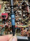
So I clipped onto r157 and

tp1 adjust L20 for 34.92500 and I read 35.1249 for am
tp1 adjust L19 for 34.9225 and I read 35.1221 for lsb
tp1 adjustct3 for34.927500 and I get 35.1269 for usb


then for the tp3 r101/tr113

lsb adjust ct2 for 7.7975 and i get 34.7621
usb adjust ct1 for 7.802500 and iget34.7669
am adjust L17 for 7.800 and i get 34.7469


What am I doing wrong to get these readings never had this happen.

Would changing the pll to the mb8719 and the xtal to the 11.1125 change these readings??

An external freq counter shows all is good but with the in circuit I just cant get any correct readings.

thanks for any help
 
Last edited:

The datasheet (if you want to call it that) shows the 8719 and the 8734 as nearly equivalent chips. The only difference is the 8734 I does not have P6 accessible.

With a carrier crystal at 7.800MHz (AM), you should not be setting the VCO to 34.925, you should be setting it to 34.985 (ch19). Here’s why: 27.185 + 7.800 = 34.985MHz. This has nothing to do with the tripler crystal and everything to do with the carrier oscillator crystal. Keep this in mind as you read on. The VCO frequency is determined by adding the desired frequency and carrier crystal, the PLL and tripler must simply agree with it. In other words, swapping tripler crystals does not change what the VCO needs to output. It only changes what the N code needs to be.

With the MB8719 PLL and stock rotary encoder, you can use either crystal, the 11.1125 or the 11.325 and still have the normal 1-40 depending on the state of pin 10 (P6). But since the 8734 does not provide access to P6, you can only use the 11.1125MHz crystal with the 8734. Since you have the 8719, I will try to explain…

For the 11.1125MHz crystal:
On AM, it is set to 11.111666 (which triples to 33.3350MHz)
On LSB, it is set to 11.110833 (which triples to 33.3325MHz)
On USB, it is set to 11.112500 (which triples to 33.3375MHz)

For the 11.3258MHz crystal:
On AM, it is set to 11.325000 (which triples to 33.9750MHz)
On LSB, it is set to 11.324166 (which triples to 33.9725MHz)
On USB, it is set to 11.325833 (which triples to 33.9775MHz)

Normally we set these by watching the VCO output because the tripler is driving a mixer and probing there can pick up the mixer products. The VCO output is filtered and is just one clean signal there. That VCO frequency is (N x 10kHz) + tripler freq (or the TX frequency +7.800 in AM).

Focusing only on AM for the moment, Sams puts the binary for ch19 at [1]0100101 (the digit in brackets is P7 and is internally driven to the opposite state of P6). So that’s N=165 for the stock Washington. If N=165, then 1.65MHz+tripler freq = VCO, and in the case of the original crystal, 1.65 + 33.335 = 34.985. Just what we needed and expected for ch 19!

But what happens if someone uses the 11.3258MHz crystal to get the uppers? Can we still get the regular channels? Well, it turns out that if you use the MB8719 and force pin 10 on the PLL high (that’s binary input P6), all else being equal, dial still on ch 19, the binary becomes [0]1100101, the N code is 101, so now 1.01MHz + 33.975MHz = the same 34.985MHz! We moved down 64 binary steps and reduced the VCO by .64MHz, which happens to be the same amount the tripler frequency went up by when swapping crystals, so it works out. The tripler crystal changed and the N code changed accordingly, but the VCO frequency is the same, which is what we needed.

Since you have the MB8719 in there, check the state of P6 (PLL pin 10). That will tell us where to go from here.
 
Pretty sure swapping the MB8719 in to replace the MB8734 you'll need to isolate pin 10 from ground and connect it to somewhere between +5 and +8 volts. But I could have that backwards, it's been a while since I've done one.
 
Well the problem was I did not have on channel 19 I was over the top of radio and i thought is said 19 but was ch 38. so i was able to get.

So I clipped onto r157 TP1

tp1 adjust L20 for 34.92500 and I read 35.1249 for am
tp1 adjust L19 for 34.9225 and I read 35.1221 for lsb
tp1 adjustct3 for 34.927500 and I get 35.1269 for usb

My problem I still have is I cannot get to the 7.8000 to read.
Im right on TP3 tr113 and I get

then for the tp3 r101/tr113 i have my freq counter at tp3 spot which is connected to r101.

is there another point for the PC-385 board
i think the below is for receive adjustments

lsb adjust ct2 for 7.7975 and i get 34.7621
usb adjust ct1 for 7.802500 and iget34.7669
am adjust L17 for 7.800 and i get 34.7469
1708297262000.png


thanks
 
What manual is telling you to align the VCO to 34.925 on ch19 AM?
When you say the radio is working, is it working on frequency?

I don't know how else to put it, but when you add 27.185MHz to 7.800MHz, you get 34.985, not 34.925. 34.925 cannot be the VCO frequency on Ch19 with a 7.8MHz carrier and filter. Something is not right.

Was that manual written for ch 14?
 
One crazy Service manual for sure and thanks for the help guys!!!!

its a service manual for a trc490 pc-385 board same as a Washington.

Steps 9-10-11 just cant seem to find a good test point for my freq counter

I marked tr13 for TP3 and if you look the symbol on the pc board is not as the tr13 is installed I see that alot on radios why who the hell knows why1708304295313.png1708304441546.pngthumbnail_IMG_8318.jpg
1708304295313.png1708304441546.png
 
I think you are looking at TR18. TR13 is northeast of that.

Board layout for the 490 attached in the pdf file. TR13 should be next to C28. I would have circled it, but my software is proving somewhat noncooperative tonight.
 

Attachments

  • TRC-490_layout.pdf
    932.3 KB · Views: 6
  • Like
Reactions: Ghetto
I did find tr13 and thanks for that as the one I located looked like tr13.

I did not have a board layout.

Still Im not getting the readings im suppose to get for step 3 4 and 5.

And again radio is working well.

this is the radio from hell

Dont know if my in circuit freq counter took a crap is an Elenco F-1000 reads all other tp but not the 103 tp
 
Last edited:
I'm more concerned about those test leads.

Seems they are "heavy" in capacitance for they drop your detected resonant frequency by loading - looks like capacitive-coupling issue.

How are those leads doing? The dress of the shielded side - what are you using to clip?
 
Here is the probe im using from my scope. I had another freq counter and sold the probe with it might of sold the wrong one as I have 2 the same.
I tried both my probes and same results cane get any reading at tp1 tr13.

I will check later today again to make sure and post back here the readings.

Like I mentioned the radio works great no problems power swr receive ssb and am all work good. Was just checking to make sure all is good had some spare time.

If this is the wrong probe what would be good to use with an Elenco F-1000 freq counter.
I have 3 inline counters and all read the same frequency spot on
 

Attachments

  • thumbnail_IMG_8338.jpg
    thumbnail_IMG_8338.jpg
    92.8 KB · Views: 6
Just a few things that need to be cleared up...

You've said a few times that the radio works well in receive, yet, your PLL is clearly out of lock and the loop frequency and VCO frequency are not in spec, so I need to ask... What exactly do you mean when you say it works well in receive? Every measurement you have made contradicts the idea that it works well in receive. What has it received for you to determine it works?

What do you mean you have three frequency counters in line? Why three? Thats just more load capacitance to try to develop signal across.

At the 7.8MHz test point you can't detect, you have a 15pF cap (C76) in series with the probe series capacitance (the maybe 10pF across the 10M resistor), that combined series equivalent is about 6pF. Now look at the other side, you have something like 30pF of cable capacitance in parallel with 35pF input capacitance on the counter and whatever the compensation cap is set to. Thats like 80-100pF total. How much signal will be developed across 80pF when it is being driven by 6pF? About 7% of the signal will be seen by the counter. This is where low capacitance active probes shine.

Looks like that PLL has wires hanging off it. I hope it is set to behave as the original PLL was intended to, at least until the alignment is finished.
 

dxChat
Help Users
  • No one is chatting at the moment.