• You can now help support WorldwideDX when you shop on Amazon at no additional cost to you! Simply follow this Shop on Amazon link first and a portion of any purchase is sent to WorldwideDX to help with site costs.

AMP SUPPLY LK500, LOUD POPPING SOUND

cbkidd1

Well-Known Member
May 3, 2005
840
155
53
61
pa.
If I did not have bad luck with electronics I would not have any luck at all. So I have a president AX144 radio that has been redone by loosecannon. By the way if not for his generosity I would not have a radio to talk on right now. He placed a relay inside so I could key the lk500. So I finally got to use the lk500 with the radio yesterday everything was working right my SWR on input was 1.1 output SWR the same. Radio keying 4 watts going into the amplifier coming out I was seeing pep around 250 watts from the amplifier. Working very well until today. I always check my SWR first thing before using my equipment. I gave the amplifier 10 minutes to warm up SWR 1.1 input and output I was talking and out of nowhere, I hear this very loud bang. The cover was off the amplifier at the time. I was looking right at the tubes when it happens. Scared the living crap out of me there was no spark or smoke just a very loud bang. No smell coming from anywhere (n) 
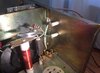
The sound sounded like it came from the right rear of the amplifier were the two tubes are located? Could one of the 3-500ZB tubes have gone bad? Do they make that kind of sound when they do go bad? Please, I really could use help on trying to figure out what happen to the amplifier. From what I can see there are no parts that look burned. Everything looks normal. The tubes were bought last year on 06/19/18 from K5SVC US government surplus as a matched set. 73,
 

I did some more looking around inside the lk500 and found what I think is a resistor? I guess this is what caused the loud bang? Looks like the white wire starts at the PB-800 Power Supply board and runs back to that resistor then over to a choke then onto the coil that leads to the Parasitic resistors which go to the filaments on the 3-500ZB tubes. The power Supply looks to be in good condition. My question is what caused that resistor to go bad and explode or was that sound one of the tubes? I hope the tubes are still ok? I don't want to go messing around inside the amplifier until I hear from someone that has experience with this type of amplifier. I came to close to death once before from my Henry 2KD5. Hopefully, someone can help me fix it. I would appreciate it. 73, Almost forgot the pictures I took of the damaged resistor.
 

Attachments

  • 56976874_310671166228621_5737192587870076928_n.jpg
    56976874_310671166228621_5737192587870076928_n.jpg
    33.7 KB · Views: 151
  • 57434212_2289420671345738_2734798435495444480_n.jpg
    57434212_2289420671345738_2734798435495444480_n.jpg
    27.1 KB · Views: 150
I hope someone can help me? Here is a picture I took of the schematic to the lk500 amp. Maybe someone can tell me what the part is that failed?
 

Attachments

  • 56828092_2202028086557885_2169743110580469760_n.jpg
    56828092_2202028086557885_2169743110580469760_n.jpg
    32.4 KB · Views: 135
Appreciate the detail but the pics are a little too close up. Yeah, I know always something to bitch at.

I will hazard a guess. Not many (okay a total of two) of the LK500 that I've seen came with a "glitch resistor" (or choke) as a part of OEM suicide prevention. Most web photos I see don't have the part either . The whole sacrificial choke thing is well documented.

Whomever added that part saved you a whole lot of pain. Now instead of replacing a bunch of parts you just have to find out if the sacrificial part was underrated or you have other problems.
 
Thank you Kopcicle, Someone else told me also that it sounded like it was a glitch resistor that had gone bad. The white wire that goes to the let's say it is a glitch resistor starts at the new PM-800 power supply. And then to the glitch resistor which I had forgotten to mention is also connected to two standoffs that are grounded to the back side cover of the amplifier. From there to an I want to say a black choke? There is a number on it RH50G143H from there to the Parasitic resistors onto the tubes. God, I hope you are right about the saved me a whole lot of pain?
 
I went ahead and took better pictures for you. Trust me Kopcicle I am in no way Bitching. I am grateful for the help. Let me know if these are better pictures.
56927170_371271937050279_6528313005308903424_n.jpg
57277824_276054383331346_9085370094774648832_n.jpg
 

Attachments

  • 57168354_327559061236633_8088605148554723328_n.jpg
    57168354_327559061236633_8088605148554723328_n.jpg
    41.2 KB · Views: 130
KOP: I am like you appears to be a mod of some kind.
However looks confusing.
The white wires (looks like Silicone insulated HV wire) coming from where?
I know CBK1 says one starts on the PS board and has the
PM-800 Harbach upgrade. The key to me is what Letter or connection point on that board do these wires originate?
The Black 50w power resistor...looks to go to ground also from the fried resistor (or choke ?).
I also see something else which bothers me. The discoloration in what looks to be HV disc cap...going where off the top of the Plate Choke? Plate Blocking cap to Tank Circuit?
I'll keep watching see if I can help.
All the Best
Gary
 
Why did it glitch? Now that is a very scary question(n) I am hoping that maybe someone put in a less then it called for Glitch resistor maybe? I have found out by going over the paperwork to the PM-80 power supply. The white wire coming off of the power supply going to the resistor is a high voltage B+ wire:sneaky: 
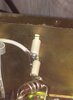
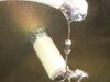
From all the reading I have done today I found that the Glitch resistor is recommended to go in series with the high voltage B+ wire;) So that has to be a Glitch resistor(y) And will explode in opening the circuit to protect the power supply or as a barrier against current. Now I need to know two things? One is what size Glitch resistor will I need to replace it with? Two what caused it to explode in the first place? (n)
 
Hi Gary,
And thank you for trying to help out. I have taken some more photo's, Maybe they will help. The white high voltage B+ wire comes off of letter k on the power supply board. Also, I took a picture of the schematic for you.
57009137_398061794111311_3272660329594617856_n.jpg
57032198_825434087807863_1350073998280491008_n.jpg
57272222_2354409541447790_7854936250225000448_n.jpg
57262712_2152451584838641_8204092391032881152_n.jpg
56949228_439580466789891_2096630230193012736_n.jpg
57221199_168308517435096_5288529287538802688_n.jpg
56764686_589307984913826_3554647348011335680_n.jpg
56744659_410873729470823_1660936459785338880_n.jpg
 
There are two red disc caps between the top of the plate choke and the white ceramic pillar, soldered side-by-side in parallel.

Pry them apart and see if you spot a scorch mark where they touch.

We learned the hard way to lean two caps like this away from each other. The voltage breakdown rating on the capacitor is a lot higher than the insulation breakdown of the shiny red outer coating. Placing them in parallel like this, close enough to touch can break down the insulation of that outer coating and get you that loud bang.

Can't make this out from the pics, but have a look and see if I'm right.

73
 
Good Afternoon Chris, As always glad for your help. I prayed the two red disc caps apart. There is no scorch mark anywhere on the two caps. I guess that is a good thing? I left them spread apart.
 
Glitch resistor" two ways this can be done, (1) With a 0.68 ohm 1-2 watt resistor in the B+ line, which acts as a "fuse" should a internal tube "flashover" or a parasitic happen, the resistor will explode opening the circuit and protect the PS. (2) A 50 watt, 50 ohm power resistor is used, to limit the B+ current by brute force and is designed not to "fuse". Some amps have an electronic plate over-current circuit, which is a good thing, but a "glitch" resistor is still needed.

This may be what was done...This info from W8JI was best description I have found for what I am seeing.

He further goes on to say:
The best glitch resistor is a pulse rated resistor. That would be something like a RCD 175P style.

http://data.rcdcomponents.com:8080/rcd/rcdpdf/100-FA039.pdf

a few 175P resistors in series will handle any fault with enough time to open line breakers or fuses in a 1500 watt amplifier.

In that same discussion he states:
0.68 ohm 1-2 watt resistor in the B+ line, is to great and does not recommend this method...
Best I've found
All the Best
Gary
 
Gary, I happen to have on hand a 5 watt 0.75 ohm ohmite axial 5% lead power resistor. I guess that would not take the place of the burnt Glitch resistor? Untill I get the right one.
 
Besides the Glitch resistor being the only part I can see Physical that is burned. Would be the tubes which I can not check(n)
 

dxChat
Help Users
  • No one is chatting at the moment.
  • dxBot:
    Tucker442 has left the room.
  • @ BJ radionut:
    LIVE 10:00 AM EST :cool:
  • @ Charles Edwards:
    I'm looking for factory settings 1 through 59 for a AT 5555 n2 or AT500 M2 I only wrote down half the values feel like a idiot I need help will be appreciated