• You can now help support WorldwideDX when you shop on Amazon at no additional cost to you! Simply follow this Shop on Amazon link first and a portion of any purchase is sent to WorldwideDX to help with site costs.

AMP SUPPLY LK500, LOUD POPPING SOUND

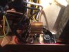
My intuition about the 'SNAP!" would be a tube with gas in the vacuum.

Or a loose grid wire that only touches the cathode intermittently. Tough to find without a continuity tester fast enough to respond, clipped between one grid and one cathode pin. We use our 'octopus', slapping the tube gently on the side, turning it from vertical to sideways. The CRT display is fast enough that even a brief short from a loose grid wire is visible.

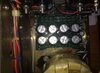
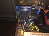
Here's the approach we chose to use a Heathkit SB1000 as a tube tester.

coxixX.jpg


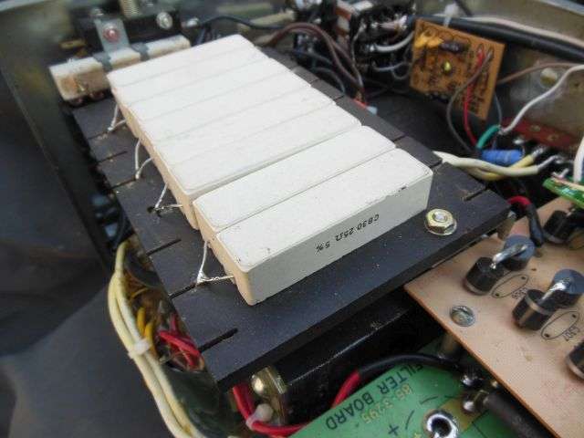
The original 3-Amp rated HV rectifiers got upgraded to 6-Amp parts. The eight 25-ohm 30-Watt resistors add up to 200 ohms in series with the plate supply. It will drop less than 100 Volts max from the HV that reaches the tubes in normal use. It limits the surge current from a 3000-Volt source to 15 Amps, not enough to damage the rectifiers so long as the circuit breaker trips fast enough. The total 240-Watt rating of eight resistors isn't valid to load them that way with steady current. Crowding them together like this reduces the exposed surface area. All they're meant to do is take a very brief overload in stride.

Eimac says that to protect the 3-500Z you should limit the current into any pin of the tube to about that value.

But it's really about protecting the amplifier from a tube, not protecting the tube itself.

It's handy for finding out how "weak" a tube really is when run by itself.

73
 
Last edited:
well maybe but according to Tom/W8JI the .68 ohm/2w is too large. The current required to blow that is way to great. However your going the right direction with the .75 Ohm but the wattage level is to high(5w)
The Drake L4B uses a .82 Ohm 1/2 watt for the same purpose. So going up to a 5 watt I think maybe ill advised.
MHO
Gary
 
If I was to replace the glitch resistor what would I buy to replace it? Chris, I have a continuity tester. Is there any way I might be able to test the 3-500ZB tubes? Should I also be looking at the tube sockets for anything? I have checked the pins on the tubes no overheating on them. Should I install one tube at a time to find the bad tube? I am no tech that's why I ask. 73,
 
After close inspection of both 3-500ZG tubes. I found there are two leads that come down from the middle of each tube not sure of the pin numbers they are soldered to? Anyway, On the one tube, It looks as if there is no solder holding the lead to the pin. I started to shake the tube and I could hear something rattling inside it. The other tube looked ok and did not rattle(n) Could it be that that tube is bad? The gentlemen AL, over at Maf technologies who I bought the amplifier from told me when I bought it that the Machlett 3-500ZG tubes. He bought from K5SVC IN 4/18/2018 had a one year warranty on them. And only maybe put 10 hours on them. There are only 5 days left on the warranty. Since I am not the one who bought them can I still get a replacement tube since I own them or will AL need to contact the seller of the tubes?
 
Before we'll plug a 3-500Z amplifier into a power socket we check each tube with a high-voltage breakdown tester. If the vacuum is okay, there won't be any leakage current through the tube when it's cold and out of the amplifier. If gas in the tube's vacuum breaks down and shows leakage current much below 3000 Volts that tube may flash over when it gets hot and cause a giltch resistor to pop.

The two pins on the base of the tube closest together are the cathode/filament. The three widely-spaced pins opposite the filament pins are all three connected to the tube's grid. A check for continuity from either of the filament pins (won't matter which one) to any of the three grid pins (also won't matter which one) will reveal a short between the grid and cathode. The "gentle slap" test serves to reveal a loose grid wire that only shorts out when it feels like it. The thin wires on the tube's control grid are spot-welded in place. If a spot weld fails, the loose end of that wire will "curl" when it gets hot and bridge the gap between grid and cathode causing a short. Likewise, if it's loose enough the vibration of the 'slap test' can make it give itself away to a continuity test.

Continuity testers are not built to a single standard. Some of them will respond instantly to a brief short. Others have a delay and won't show a short that only occurs briefly while slapping the tube around.

If you have a pocket full of glitch resistors you could try the tubes one at a time. A tube that pops that resistor by itself is definitely bad. A tube that doesn't pop the resistor MIGHT be okay.

Even then you still need two tubes to run the amplifier. Won't behave properly with only one. Replacing only one presents another problem. If the "good" tube has any mileage on it, that tube will be weaker than a new one. A mismatch of this kind will cause the newer, stronger tube to run hotter than the weaker one. If you don't throttle back the power, the new tube will overheat and fail prematurely.

I wouldn't be using the fancy tools for this if I could get the same result from the cheaper, simpler tools.

My copy of the Drake L4B manual shows a glitch resistor that is 0.82 ohms at 2 Watts. A notation on the schematic says to use only "IRC type BWH" resistor only.

Most any 1-ohm 2-Watt resistor is probably close enough.

73
 
Hmm. Looks like your last post went up while I was typing the previous one.

If the solder has melted inside the tubes' hollow chrome-plated brass pins this suggests the socket has a problem. There is a hairpin-type spring wrapped around each socket contact that maintains tension against the tube pins. If the surface of the contact becomes oxidized, or the spring loses its temper, you'll get heat from the poor contact against the tube pin. A loose tension spring and/or oxidized contact surface cause a high resistance. Turns that 14.5 Amp filament current into heat.

Usually happens to the filament pins first, since they have the most current through them.

Pretty sure melted solder inside the pins won't be covered by warranty. You'll probably get told that keeping clean-and-functioning sockets in the amplifier is your responsibility.

Any kind of loose stuff inside the tube rattling around is all wrong.

Sounds as if it might be time for new tubes and (this time) new sockets

I'll guess that if you take a bright light and a magnifier to the filament-pin contacts on those sockets you'll find the metal-contact surface is no longer shiny and clean. That alone can release enough heat to melt the solder in the tube's pins.

I have seen a sequence play out that I call "socket ping-pong" in 3-500Z amplifiers.

Starts with a tube that has a dark filament. Lights up when the tube is jostled in place. This generally indicates that the solder inside the tube's filament pins has melted. The heat from this fault ruins the shiny surface of the socket's filament-pin contacts.

The owner replaces the tubes, but when the new ones go bad because of the bad sockets, he brings it to me. I replace the bad sockets and tell the owner to buy a new pair of tubes.

He ignores my advice and continues to use the damaged tubes until the filaments won't light any more. Of course, this damages the new sockets. He finally buys new tubes, but only after damaging the new sockets. The new tubes will now be damaged by the socket problems he caused by using the old, damaged tubes.

Lather, rinse, repeat.

A partial solution that seems cheap in the short run tends to have hidden costs that appear later.

73
 
Afternoon Chris,
Well, I got the new 0.82 OHM 2 WATT 5% RESISTOR today. and soldered one in the amp. I prayed it would work. Then I turned it on only to find out that the plate current was only showing around 2500 volt when it was showing 3200 volts. So I knew something was not right. So I switch the amp off and was hearing like a ticking sound. I started looking around and found it coming from the main peter dahl transformer and seen that it was coming from under the transformer. Or were the wires come out of it. I think the 0.82 OHM 2 WATT 5% RESISTOR did more damage to the amp? I feel like I am going to be sick.It cost me 1,200.00 and almost everything inside was replaced. I don't know if it caused more damage or not. I put the resistor in with the gold line facing down like the old one was. I don't understand what went wrong this time? That was the first time it had been turned on since the old resistor burned up. Do you think the new resistor caused it or was it that way after the old resistor went up? My best bet is just too quite the hobby and sell it all. I don't really want to. I have been doing this since 1974but I just don't have the money being on disability to send it off some were to be fixed. Going to miss people like you and Matt and talking skip my favorite thing to do lol. But don't know where to start and what to do to start repairing the amplifier. I can't wait to hear your thoughts on this. I like the store you were telling me about working on the auto assembly line years ago.
 
Putting an amplifier this old back into regular service works better if it was not mistreated over the previous 30 or 35 years. Trouble is, how do you tell that?

Any time we see this kind of behavior the usual approach is "divide and conquer".

Hooked up all together, the amplifier's parts behave in a puzzling way. Unhooking and checking separate parts of the amplifier can only narrow down the fault if you have a way to test them that way.

Trouble is, coming up with a way to prove the tubes are good calls for an amplifier (or tester) that you know is (itself) good. The tubes would either pass or flunk, but that part of the picture would get filled in.

Anything like noises or smoke coming out of the transformer would be a real disappointment. That part is really pricey. Unhooking it to check for insulation breakdown now calls for a HV-breakdown insulation tester. This will tell you in a positive way if the transformer's internal insulation has failed.

Tough to pin down this question without one.

The "glitch" resistor was *NOT* a part of the original amplifier's design. Someone added it as a safety feature. It's a fuse, nothing more.

The only way you can blame a breakdown on a fuse is to make the fuse too big. Adding a fuse the designer left out will never create a failure issue.

Never.

Considering that this "fuse" was not even included when the factory shipped it, that resistor is surely not causing any of the grief here.

On the other hand, if someone operated it with one sort of overload or another inside it and put fuses that were TOO LARGE in the holders, this could create hidden damage no matter how new the power-supply parts are. And once the "no-blow" fuses get removed, and the correct size put back, there's no evidence that this kind of abuse may have happened. Until a transformer shows the signs of wear and tear that this caused.

Sometimes a simple problem can be pinned down and remedied with simple tools.

Sounds more and more like this amplifier's troubles are not so simple.

73
 
  • Like
Reactions: Shadetree Mechanic
I took a few pictures so you might get some ideal as to how he rebuilt the amp and thing he added. The peter w dahl transformer was rewound by Garry Brown?
 

Attachments

  • 57262712_2152451584838641_8204092391032881152_n.jpg
    57262712_2152451584838641_8204092391032881152_n.jpg
    46.7 KB · Views: 182
  • 57484541_2187805521273678_3391022799274377216_n.jpg
    57484541_2187805521273678_3391022799274377216_n.jpg
    41.7 KB · Views: 164
  • 57595628_2023529601107089_2460311288971001856_n.jpg
    57595628_2023529601107089_2460311288971001856_n.jpg
    40.7 KB · Views: 164
  • 57840013_2792613454099140_6999653075833061376_n.jpg
    57840013_2792613454099140_6999653075833061376_n.jpg
    37.1 KB · Views: 125
Umm, uh.... Yeah!

I'll venture a guess that whoever customized this amplifier did not supply a schematic diagram.

It's tough to make sense of a custom setup without some sort of road map.

And the setup in this one is definitely custom.

Unwinding just what's in there, and making sense of it calls for one very particular set of skills. Anyone with the experience to put this thing together can probably sort out what's going on in it. And if you're not qualified to build it in the first place, making sense of it will be an uphill struggle.

The factory diagram is clearly not much help making sense of this amplifier. That's about the only thing the pics make clear.

We have a nickname for this kind of amplifier when a customer shows up with one. A "nightmare box".

Might not really be that bad. Not sure how you could tell from a distance, though.

73
 
There was clearly lots of work done to this amp that was pretty much NG. The intentions may have been good but the execution was all wrong. The original design calls for the correct type of glitch protection and a simple look at the original schematic should suffice to renew the plate section of this amp. It is not rocket science. The blocking cap looks like it let out the magic smoke so that will need to be replaced with the proper replacement type blocking for the job. If the transformer was rewound by Gary Brown, he generally does good work but last I saw the business is for sale and he is getting out. Haven't checked lately if someone took over or he closed shop. As far as the tube pins coming unsoldered, that needs to be determined if that happened from abuse or if the tube socket pins are actually bad. A visual inspection of the underside of the tube socket will quickly determine what happened. If the power transfomer is still good and Gary didn't goof up the rewind, this amp will need about a couple of hours work and a new tube (or good used) and it will be back on the air. Not a total loss unless the transformer is bad again. That little tiny resistor that blew out is barely enough to keep the amp running at a normal pace. Totally wrong and the big one under it is the wrong type as well. Sorry for your loss but it can be revived in short order with some TLC barring that transformer issue.
 
Afternoon BlowinSmoke,
The amp was working fine the first two times I used it no trouble. Then like I had said I heard that loud pop sound and shut the amp off to avoid any damage to the amplifier. And seen that the glitch resistor had burnt up. I then got help with what I should replace the 1/2 watt 0.82 glitch resistor with and was told to use a 0.82 2 watt resistor. So I just received the 5 new 2 watt 0.82 glitch resistors used in the drake l-4B and installed one. After the install, I turned on the amp and seen that the plate voltage was only at 2500 volts, not the 3200 volts. So I then turned off the amp. I then was hearing this very low popping sound sounded as if it was coming from the main transformer? I don't know if maybe replacing the glitch resistor would chance the plate voltage? The only sign of anything happening was the burnt glitch resistor no smoke ever or could I find and other burnt wires or parts? I am going to post what had been done to the amp from the person in his own words. Maybe that will help or give someone an idea of what might have happened? If I could repair it with the help from you guys here on the forum that would be fantastic. As I really don't have the money to send it off to be fixed right now. Thank you all for taking your time and expertise to help me with trying to fix the amplifier. I appreciate it so much.
 
Here is a copy of what had been done before I bought the amplifier.

Now the story with the one I am selling: I bought it in a 100% cosmetic shape with a busted HV power supply, shorted transformer, no tubes, busted Vernier, bad fan – which cause the meltdown! Dumb owner kept going with no fan how stupid do you have to be to do so?.


I loved the front of the amp so I bought it as is. I love fixing amps!


1- Took it 99% apart and removed the power supply section

2- Shipped the Hypersil transformer – yes hypersil! (Drake used regular ones) to Gary Brown in Maine to rewind it for a higher HV voltage. Gary Brown is the top US guy to fix Peter Dahl transformers. It came back new, fully vacuum dipped and it performs amazingly well.

3- Installed a new set of 3-500Z tubes STILL UNDER THE YEAR WARRANTY

4- installed a new Vernier

5- installed a high flow fan

6- replaced the power supply with a brand new harback board new caps and bleeding resistors

7- rewired beautifully the whole power in section

8- installed 2 x 20A thermal breakers instead of the dumb fuses everyone uses

9- added QSK!!

10- Vacuum relay for QSK

11- Added a soft start board

12- Added a 3 minute vox delay so you can’t key the amplifier with cold tubes (and blow them up!)

13- Added +B protection to protect the power supply if a tube ever shorts

14- Recalibrated all tuned inputs (what a job!) to minimum swr so the exciter almost look at 1.2:1 swr

15- New power cord amp wired for 240V.

16- Other stuff I do not remember


So basically this is a new unit in beautiful cosmetic shape that was built like a tank the way good amplifiers were built in the past.
 
OK fine, assuming everything HE did was done right you don't have to go to the primary side of the transformer looking for problems. Your problems are on the secondary side. Your next move is to check out the rectifier and verify right at the take off of the B+ at the PS what the voltage actually is there. It should be around 3200 I am guessing but certainly 2500 is too low but that could be a metering problem in the amp HV metering circuit so you'll need an alternate method of checking the B+ leaving the PS to the tubes area. At this point in time you should not worry about even connecting the B+ line to the tube area. First verify what is coming out of the PS and see if the PS now needs work. Don;t worry about the tube area now. When you get an accurate measurement on the B+ report back.
 
  • Like
Reactions: Shadetree Mechanic

dxChat
Help Users
  • No one is chatting at the moment.
  • @ Wildcat27:
    Hello I have a old school 2950 receives great on all modes and transmits great on AM but no transmit on SSB. Does anyone have any idea?
  • @ ButtFuzz:
    Good evening from Sunny Salem! What’s shaking?
  • dxBot:
    63Sprint has left the room.
  • dxBot:
    kennyjames 0151 has left the room.