• You can now help support WorldwideDX when you shop on Amazon at no additional cost to you! Simply follow this Shop on Amazon link first and a portion of any purchase is sent to WorldwideDX to help with site costs.

Another 139XLR power supply problem.

Are you talking about the wire going from the emitter of the TR302 to the base of the TR401?

I was wrong about unhooking the base lead expecting the 14v to be there on the wire. The voltage reference part is powered from voltage coming from the 401, so turning off the 401 would also turn off the reference source.... My bad. \I would just check the 401's BE and BC junctions with a diode tester and go from there.

Im betting the B-C junction of the 401 is toast.
 
To make sure the transformer didn't open up - take a 914 Auto bulb to the output of the bridge rectifier that negative and positive and see if the lamp leads can light up across it - if it doesn't the transformers windings opened up or it's wired wrong to the supply.

The supplies dies when a load is placed on it, the transformer is wired wrong to it or the winding in it has opened up - unable to supply enough current to make it work.

Best to check the ability to load first.
 
I also did this to help you...
This is redrawn so you can see it better and also to "fix" some errors in the OEM draw, mostly being that D301 and D302 are Zener types and that TR301 was drawn as an PNP - it should be an NPN.

The other effort is to show that the power supply - being as basic as it is - is quite unique in the application of "limits" D301 (6.2V) and D302 (16V) "set" a window of adjustment using RT301.

This type of regulation is "follower" type - where the system output is "monitored and regulated" thru sense tap in the output.

TR301 "looks" at the output power thru a divider circuit using R302, R301 and Variable RT301 - the variable is set in the middle of the two fixed resistors forming and upper and lower limit in both sense and power limiting so the NPN doesn't overheat - but the voltage divided down is 1/2 the supplies output - which is applied to the Base - which is "compared" to a known reference D301 - a 6.2V Zener and the input to supply the power to drive the Pass Regulation is limited to 16V thru D302 so the "window" to drive the system is maximized to one value and "dropout" is set to a lower value (D301).

This does not mean the system is foolproof.

RT301 can open up and therefore TR301 "quits" - so I would suspect the Variable has opened or somehow got too dirty and opened up in the circuit - killing regulation.
 
  • Like
Reactions: Rwb
I just pulled TR302 and TR401 Both tested good. I am only getting 8v and 9v out of TR401 I should be getting 14V and 15V it must be something I screwed up. It was working.
 
Sure don't remember this regulator circuit. Where is the current source for D302? I'm used to seeing a resistor from the unregulated rectifier output to the cathode of this zener. D302 can't regulate 16 Volts to the base of TR302 without a current source.

73
 
Comes from this schematic

CBTricks>>RADIOS>>Cobra>>139XLR >> "Look for" COBRA139.JPG

1650884398355.jpeg
Specifically ... here...


1650884460790.png

That current is supplied by R305

I drew it wrong...

Should be more like this...
1650885122948.png

Good eye sir...
:unsure:;)o_O
 
RT301 is about the only thing that has not been changed. It is kind of screwy when moving it. Nothing about how to adjust it in the Sam's. Could that be the problem and I am overlooking it?

The origional problem was when I plugged in DC some wires on the power supply burnt. I rebuilt the power supply now the DC external works but the power supply does not work. This is totally weird. Pardon errors I am doing this with my phone.
 
I have been using Sam's photofacts. Voltages on every part I check are good except the regulators and I am only seeing 9V max output. Andy you mentioned transformer. I do not have the bulb here that you are talking about but I get 12.5V on each wire coming off the transformer to the Bridge rectifier. then from the bridge to the board 25V like the schematic shows. I do not think it is the transformer. And it was working.
 

Attachments

  • 20220425_075951.jpg
    20220425_075951.jpg
    1.9 MB · Views: 6
Last edited:
I guess I could try to explain how the entire circuit functions (perhaps andy could double check me here) as it might help you track down the problem.
----------------------------------------------------------------
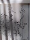
When the mains is plugged in, the rectified voltage initially goes through R305, is clipped by zener D302 to 16v, then that 16 volt is fed via R304 to the base of TR302. This begins to turn on TR302, which in turn, begins to turn on TR401. At this point, TR401 begins to pass voltage on to TR301's base via the divider network. Once the voltage on the wiper of RT301 reaches 6.7v (because the zener D301 keeps the emitter at 6v), it begins to turn on and pass current to ground that would otherwise be helping turn on TR302 ~ in other words, it tries to turn off TR302 a little. At this point it is a balancing act between the base of TR302 and the collector of TR301 taking current from R304. Its a feedback loop. Because the zener D301 is holding the emitter at 6v, the base wants to stay at 6.7v no matter what. Therefore, the variable resistor RT301 does not change the voltage at the base of TR301, but rather the amount of current that can go through the base, which in turn controls the amount of current through the collector. This establishes a voltage drop across TR301's collector-emitter pins that, when added to the 6v zener, should equal the 15v needed at the base of TR302. However, don't assume that just because it is not currently at 15v that TR301 is the problem, the problem could be elsewhere.

With respect to TR301, I will speak in terms of voltage as it is more intuitive for understanding the resistive divider, just know that its really the current changing at a steady base voltage.

This TR301 is like the sams schematic says, it's an error amplifier, because under normal circumstances, if the voltage on the output were to change, the voltage that would otherwise be on the wiper of RT301 would change (had it not been connected to that base lead and held at 6.7v). This changes the current through TR301's base in response to deviations in output voltage ~ it tries to keep the output the same by adjusting the regulator opposite to the changes caused by the load. For example, if the output voltage were too low (under normal circumstances), the voltage on that wiper (had it not been connected to the base) would be lower. This means less current is forced through the base as it tries to hold it at 6.7v and the transistor is trying to turn off. With this transistor pulling less current away from R304, more goes into the base of TR302, which raises the output.
------------------------------------------------------------------------
Perhaps you could test the transformer with, alternatively, a pair of small automotive turn signal bulbs in series as andy suggested just to ensure it can output that 25v under a reasonable load... But with there being 25v on the collector of TR401, I don't think that is the problem (as a lack of current capability would drop that 25v all the way back to the rectifier).

You say all the transistors are working and everything was replaced, I would then suspect the current gain of the replacement you chose for TR302 as it has a lower Hfe than the original part (and thus draws more of the precious little current available from R304). Did you also replace C302? It might also be possible that it is leaky and is gobbling up the little current available to drive TR302. Temporarily pop that cap out and see if the voltage goes up.
 
Last edited:
Brandon I tested Tr302 on my Peak Atlas DCA55 and the 2SC1419 that came out of the power supply. The TIP41C had a higher base emitter voltage. .70V compared 20 .60V on the C1419 and the TIP also had a higher HFE. so I reinstalled it. I could try another but with the readings I saw I figured why bother
 
  • Like
Reactions: brandon7861
Between the two TR401 and TR302 - TR302 "mirrors" so it pumps TR401 to add in extra ability to pass current.

TR301 - see the output and regulates to the Zener and divider drop differences.

When the power supply sees a voltage increase the output - TR301 regulates "less" power dropping the power TR302 pumps into TR401 - that 16V Zener sets an upper limit - your real regulation is D301 - that 6.2V Zener - if that is bad - you're stuck...

When the power demand is higher - naturally the voltage drops - so D301 regulates less - increasing power into TR301 to Make TR401 work harder.

Got any spare 6.2V 1W zeners?

When you measure at R301 (that 330 ohm) you should have 4 to 5 volts all the time off of one side, and zero on the other leg of the resistor (the one to ground)
 
Only way I ever learned to get a result from this kind of circuit was to unhook and test every semiconductor in it. And replace any electrolytics.

Found that if every zener, every transistor and diode all tested okay, it would usually work.

73
 
Right voltages?

Well, if all the parts check out, it is a 9V power supply...but it supposed to be a 13.2V power supply for a Radio.

Something is not right.

1650971371025.png
 

dxChat
Help Users
  • No one is chatting at the moment.