I Thought it was working when removed from the truck. I switch radios quite often. It has been sitting on the shelf for a long time possibly a year. I was going to put it back in the truck Mon I put it on the bench to test it and this. So not sure what or when. I do know my match is about the best I can get it at 1.4 to 1.5 Everything else has lasted including Cobra 29 with stinger board. I am hoping I can still get a matched set of transistors.

You are using an out of date browser. It may not display this or other websites correctly.
You should upgrade or use an alternative browser.
You should upgrade or use an alternative browser.
-
You can now help support WorldwideDX when you shop on Amazon at no additional cost to you! Simply follow this Shop on Amazon link first and a portion of any purchase is sent to WorldwideDX to help with site costs.
-
A Winner has been chosen for the 2026 July 4th Retevis RA89R Giveaway! Click Here to see who won!
Another radio falls victim of Bob's CB shop
- Thread starter Low_Boy
- Start date
@Handy Andy
Yes, I would have thought that the FETs would have the same requirement.
But overall it makes sense.
Super funny, I made my GF read this as she got a kick out of it from the comparison!!
they use Bias feeds for EACH transistor
Yes, I would have thought that the FETs would have the same requirement.
I'm not totally familiar with this configuration (except for class where it was discussed in three way phasing with a compare and contrast with delta configs).Y-wye configuration
But overall it makes sense.
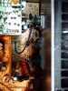
Stripped like a Chevy Citation in Bad neighborhood
Super funny, I made my GF read this as she got a kick out of it from the comparison!!

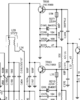
I'll let you pore over these snapshots from the CB Tricks days...

Both are Galaxy in the above but one is MOSFET while the other is a single BIPOLAR final - using similar coil winds only less winds "winded" together - it's why I call it a Wye configuration - they are using the two coil interactions and utilizing the 3 terminals - with 2 tied together at one origin - but use all three in a configuration.
similar to Wye.
You can also see the "optimization" needed to make MOSFET work well yet if not applied to an upgraded radio with the older Bipolar parts, they don't mesh together very well...
Attachments
@Handy Andy
Thank you for the schematics and explanation.
I'm going to go out on a limb here and postulate that in the top schematic feed back is via R218 (with some influence of VR11)?
And on the second schematic the feed back is via R247?
Is that correct?
Actually the GF and I disagree. She claims that the gain of these stages is mostly controlled by impedance of the coils and her evidence is the coils can not be tuned.
I maintain that the resistors have the most influence over the set impedance of the coils.
Please say I'm right -J/K!!!
Thanks in advance.
I looked at the schematics (2SC1969 version, and the MOSFET change) and you are right, they do "volt" the finals from the factory, the AM Modulator goes to the Driver and Pre-Driver. It is an AM/FM radio, not an SSB, though.
http://www.cbtricks.com/radios/rflimited/magnum_s3/index.htm
And, the schematics for the 45 Watt MOSFET version does have only one EN369FN biasing part to both Gates on the Finals.
Right, it’s not SSB. All I meant was that in my opinion it didn’t really hurt the finals because that’s exactly how they’re done in an SSB radio.
@Low_Boy Then we cycle back to the original problem...
They were not matched...
Either way, single part or not, no provision was made to balance the currents - you are better off just using a single ERF2030 in there than to try and use two - even though they claim they are matched...
@500kpot R218 is a buffer resistor - keeps RF off the Bias line. There are several paths the RF could take to generate a feedback loop from the sheer gain the MOSFET has.
So they "buffer" the Gate voltage to keep RF where it should be at the Gate.
There is also a secondary effect that Bipolars used for themselves to keep them selves clean - drink lots of current from the Bias line as a method to "stay hydrated" - on the MOSFET you need some "trickle" voltage to keep the field active at the Gate - but it takes current to "recharge gate capacitance" - so the Resistor holds back power in current limiting to keep the Gate stable but not skew or otherwise distort the RF wave and then we have IMD problems from the RF wave is no longer symmetrical. Else the Gate may stay on too long and ruin your efforts...

Ok, for those that need to review...
EN1230, EN369 FN or DR - provide power thru Rectification or trickle bias (DR is designed for this)
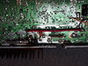
Look up to Post #19 from @Low_Boy - review the top of the board...
Note R271 is that EN part...
Note R270 is jumper....
Now let's review...

Green Arrow, R271 location - where EN part is installed
R270 - Shows jumper - Dead Short...
Where is the other final getting connected?

The only other feeder line is R217 - empty...

Here's the rub...
From Bobs' CB, customer get radio - with dual final install.
But is it a dual final install?
When you leave an MOSFET installed but not connected - it's output Drain and Source are still hooked up but the Gate has no drive - but it's sitting right next to one that is driven...
What happens next?
Echoes...Echoes....Echoes...Echoes...Echoes...Echoes...
An effect that is a mirror image of the wave generated by another only out of phase or triggered by proximity in event and power fields due to the proximity of the part...the MOSFET has a field around it and it's at the terminals but not at the RIGHT one...you still have an effect from it.
Open gates are like open leads on simple CMOS devices , they'll squeal, latch and do all kinds of crazy stuff - including self destruct if they can...
It's why TTL devices need their inputs and outputs to go somewhere else they cause triggering issues with in the chip itself.
So, anyone have an answer for @Low_Boy? Anyone - Pork Chop?
EN1230, EN369 FN or DR - provide power thru Rectification or trickle bias (DR is designed for this)
Look up to Post #19 from @Low_Boy - review the top of the board...
Note R271 is that EN part...
Note R270 is jumper....
Now let's review...
Green Arrow, R271 location - where EN part is installed
R270 - Shows jumper - Dead Short...
Where is the other final getting connected?
The only other feeder line is R217 - empty...
Here's the rub...
From Bobs' CB, customer get radio - with dual final install.
But is it a dual final install?
When you leave an MOSFET installed but not connected - it's output Drain and Source are still hooked up but the Gate has no drive - but it's sitting right next to one that is driven...
What happens next?
Echoes...Echoes....Echoes...Echoes...Echoes...Echoes...
An effect that is a mirror image of the wave generated by another only out of phase or triggered by proximity in event and power fields due to the proximity of the part...the MOSFET has a field around it and it's at the terminals but not at the RIGHT one...you still have an effect from it.
Open gates are like open leads on simple CMOS devices , they'll squeal, latch and do all kinds of crazy stuff - including self destruct if they can...
It's why TTL devices need their inputs and outputs to go somewhere else they cause triggering issues with in the chip itself.
So, anyone have an answer for @Low_Boy? Anyone - Pork Chop?
@500kpot R218 is a buffer resistor - keeps RF off the Bias line. There are several paths the RF could take to generate a feedback loop from the sheer gain the MOSFET has.
Okay got it.
Looks like the engineers left nothing up to chance. Lovely, using one part to take the operation of two, R218 is in the loop of the emitter output and returns back to the base. The innovation is astounding!!! I wish I could think like this, perhaps someday but not today.
So, anyone have an answer for @Low_Boy? Anyone - Pork Chop?
I guess I'm not allowed to post on this thread anymore??? I was just getting ready for a good discussion... My Bad...
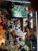
so... You think ol bob gave you the shaft?Got this magnum S3. Sealed with Bob's CB shop stickers. It was cranked to hell. Could not even get anything on the scope to look good. Parts must be changed somewhere I have to take a closer look. So like all other Bob's radios. After a few weeks one final blew.
I picked up the radio for a very reasonable price USED. Had 2 blown front end diodes. I did not get screwed at all. Just saying the radio had the stickers on it it was sealed. I was the first one in it to change the diodes. The radio is cranked way up and blew a transistor. The radio is the victim not me.so... You think ol bob gave you the shaft?
dxChat
- No one is chatting at the moment.
