I have some models. Before I get into them, you should read the full post before just taking them for what you see. They are far enough outside of my expectations that I am questioning the results myself...
The first of each pair of models is from the point of view of the side, and the second from the point of view of looking down on it from above.
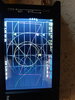
So starting with free space.
[photo=large]6744[/photo][photo=large]6745[/photo]
These are free-space numbers, and I want to stop and put these in perspective. A 10-meter band three element yagi in free-space tuned for absolute maximum gain will get 8.4 dBi forward gain, if tuned for optimal it will get about 7.7 dBi gain, and if tuned for low SWR it will get 7.2 dBi gain. This is directly out of the 23'rd edition of the ARRL Antenna Book. Unfortunately they didn't include a 2 element yagi design. In another chart, an optimal (note this isn't max gain but optimal setup) 10 meter 2 element yagi is still putting out close to 6.5 dBi free-space gain. As this model is only showing about 5 dB of gain (a little under), and the reference model is close in frequency relatively speaking, this is a fair comparison. At least as far as free-space is concerned, I would see this antenna model under-performing compared to a straight two element yagi, and without the benefits of the optimal setup of said yagi.
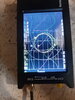
Next at 10 feet above average earth.
[photo=large]6750[/photo][photo=large]6751[/photo]
20 ft
[photo=large]6748[/photo][photo=large]6749[/photo]
And 30 ft
[photo=large]6746[/photo][photo=large]6747[/photo]
So, in free-space where I have the third party reputable source I referenced above for comparison, its not really that great. The number for being over an earth, well, even a 1/4 wavelength vertical omnidirectional antenna can be mounted high enough to show over 10dBi of gain, so take that information for what its worth.
That, however, doesn't mean that this antenna won't work well. There is more to antenna performance than just gain, but if it were me I would stick with a standard two element yagi.
All that being said, I do think it is an interesting antenna design. Where most people jump straight to "yagi", the first thing I though of was "end-fire array". While both of these setups have the same goal, that is more gain in one direction, it seems that someone tried to combine both of these very different setups, which also have very different requirements for things like spacing and element lengths and such, and because of these different requirements I think the results suffer. That being said, I wonder if there is a setup where this type of combination can be made to work... It is worth experimenting with when I get the time... I actually have a few ideas just thinking off the top of my head...
The DB
The first of each pair of models is from the point of view of the side, and the second from the point of view of looking down on it from above.
So starting with free space.
[photo=large]6744[/photo][photo=large]6745[/photo]
These are free-space numbers, and I want to stop and put these in perspective. A 10-meter band three element yagi in free-space tuned for absolute maximum gain will get 8.4 dBi forward gain, if tuned for optimal it will get about 7.7 dBi gain, and if tuned for low SWR it will get 7.2 dBi gain. This is directly out of the 23'rd edition of the ARRL Antenna Book. Unfortunately they didn't include a 2 element yagi design. In another chart, an optimal (note this isn't max gain but optimal setup) 10 meter 2 element yagi is still putting out close to 6.5 dBi free-space gain. As this model is only showing about 5 dB of gain (a little under), and the reference model is close in frequency relatively speaking, this is a fair comparison. At least as far as free-space is concerned, I would see this antenna model under-performing compared to a straight two element yagi, and without the benefits of the optimal setup of said yagi.
Next at 10 feet above average earth.
[photo=large]6750[/photo][photo=large]6751[/photo]
20 ft
[photo=large]6748[/photo][photo=large]6749[/photo]
And 30 ft
[photo=large]6746[/photo][photo=large]6747[/photo]
So, in free-space where I have the third party reputable source I referenced above for comparison, its not really that great. The number for being over an earth, well, even a 1/4 wavelength vertical omnidirectional antenna can be mounted high enough to show over 10dBi of gain, so take that information for what its worth.
That, however, doesn't mean that this antenna won't work well. There is more to antenna performance than just gain, but if it were me I would stick with a standard two element yagi.
All that being said, I do think it is an interesting antenna design. Where most people jump straight to "yagi", the first thing I though of was "end-fire array". While both of these setups have the same goal, that is more gain in one direction, it seems that someone tried to combine both of these very different setups, which also have very different requirements for things like spacing and element lengths and such, and because of these different requirements I think the results suffer. That being said, I wonder if there is a setup where this type of combination can be made to work... It is worth experimenting with when I get the time... I actually have a few ideas just thinking off the top of my head...
The DB