Very nice work Starduster, I envy you---being able to working hard with something you enjoy.
The key is to be able to make changes quickly. It only takes about 3 minutes to get the antenna down to make changes. I like to share the results and get opions so you guys are as much a part of it as I am. This is greatly apreciated.
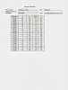
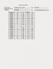
The AP Copy 5/8 R had larger tubing in different spots including the top hat and yet the frequency went higher, and was higher even than the NOS. That surprises me unless the length of the 1/4" top hat was made too short to accommodate your estimate, like you intimated in #3 of your differences section below. I would have expected the (red line) Copy 5/8 R to be the lowest in frequency just base on the facts and because with larger tubing it needs to be shorter that the NOS in order to maintain resonance.
Me too.
We can see differences, but they are not significant except for the frequencies and even that is not much, well within bandwidth range. Bandwidth range is a bit low compared to my Top One and I’m not sure yet why that is. I have not really studied my AP stuff from last summer because it worked fine and I could not tune it like the other antennas I was comparing.
I do have a theory on this but it needs further testing before I open my mouth.
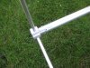
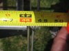
How long did you make the 1/4" Top Hat radials? Whatever it was going shorter didn’t seem to affect the frequency like I would expect with the 1/2 R. I don't get that, seems it should be higher. I guess we can't fuss to much seeing as the 5/8 R antenna is resonant almost perfect to the middle of CB band. Isn't that what you saw the very first bat-out-of-the-box with that antenna? I would set that one and forget it, and the bandwidth being near 2 mhz is perfect. That is what Avanti touted on their ad stuff, if you can find it anymore.
Yes I did see that right off the bat. But I could not get the SWR down to 1:1 with the antenna mentioned.
Well Starduster, you may be right, but at this point and with no real way to tell, maybe you should wait and see how the Copy 5/8 R works on-air and compare it to the original and/or you first Copy 1/2 R---if that is possible. I would do that before you consider changing the top element to a full 1/4 wavelength. On-air you may find something else to consider and that may take a little time. I think you have worked good and hard. You need a break. You will find if you go too fast now, you may miss something---and like me, I always regret something later going too fast.
I here you.
Did it surprise you that the 5/8 R was working at 27.200 mhz when the other day you couldn’t figure why it changed? What did you do different? I bet it had to do with the feed lines. Maybe it would be a good test to change the line to some random length on the 5/8 R, and see what, if any, affect it has on your scans. Please don't do it before you do some on-air work first and get a feel for what it does. Going fast is great and gives us a lot to talk about, but we don't want to miss the on-air testing.
I also am thinking feed lines. The early test may of been flawed. that is why I changed it.
The symmetrical stuff is really good IMO, but you might not be able to tell with the testing you are doing. Where that counts is the positive affects it can have on pattern.
Agree but that is hard to test.
I got and opinion, but you don’t want to hear it.
Let me take a stab at it; Marketing hipe?
You did good.

,