Well here we go again.
I will not quit until I get this right.
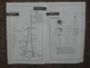
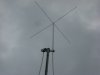
Needing a good base line I decided to assemble the original Astroplane and take good baseline readings from that. I assembled the antenna following the instructions exactly.
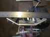
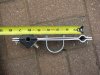
The coax used is a half wavelength LMR 400 VF=.85 as measured with the MFJ 259B antenna analyzer. The MFJ instructions recommend a coax length in multiples of ¼ wavelength The coax was made to a length of 30’ 9” so it should be close to 27.205.
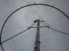
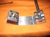
The coax runs down the mast centered between the down leg elements.
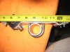
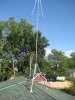
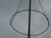
The mast is approximately 19’ in length and the nonmetallic guy are attached about 49” below the loop. There is about 112” of mast between the loop and the top of a 3’ tripod.
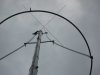
The whole assembly sits on top of the garage roof in as much free air as possible.
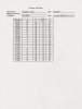
The results are as follows:
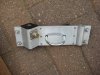
SD'r I sure would appreciate a close up of the original AP you have up now. Other than the modes to the first one you posted, are they similar? Not that it makes a difference, but these look like knockoff's like the TopOne I have.
They're a little different, because mine has an insulator type setup inside of a small piece of square tubing attached to both ends of the mounting hub, while your's has only one insulator setup that is at the feed point and the other side uses compression, just like the original Avanti. If both of your AP's are of similar construction and source, then I have never seen this particular model before. Do you know who made it? Mine is a TopOne from Coopers. I have some other random TO/AP's parts, but they are all the same source, Coopers. Just curious.
BTW, is there a type-O with the 30'9" in the text and the 19'9" on your work sheet for the 1/2 wave tuned line?
Were you surprised at these results you post today? I was, so I went back and really studded my Work Sheets for my TO. On two reports #5 & #6 for the AP in particular.
On test #5, it shows I used a make shift 97.25' tuned feed line which should be close to a resonant length @ 27.205 mhz.
On test #6, it shows I removed a 5' jumper from the mix to make the line 92.25' and non resonant.
When I went with the shorter feed line in #6, the tune (value of R & X) and the SWR got worse, the bandwidth got much narrower and went from 3.16 mhz down to 1.95, while the resonance stayed about the same on both.
This was surely not a scientific testing feed line, because I used barrel connectors to put jumpers together to make that length, and of course there were mixed VF to consider. I violated all the rules, but it looks like that is what I did.
The big deal was the resonance was at 27.005 mhz, almost what you're showing in frequency with your tuned line. I don't think I ever posted my work sheets for my AP, because I have not really studded them and made notes, but I think I will do that soon and post them with my other Antenna Work Sheets in my albums. It also looks like when I used a purely random feed line, like 76' which I use now for a working line, both the top hat and the straight 1/4 wave models tune at 27.205 almost on the button and in both cases the BW is wide in the range of 3mhz with the full 1/4 wave showing above 3 and the top hat model showing a little less at 2.88 mhz. The tune on the full 1/4 wave is also much better by the numbers and the SWR, but on-air I recall I was not impressed. Maybe it was a difference in the angle of radiation that I was noticing and I did not study or realize it at the time.
Hopefully Bob85 will be testing this idea soon, with his homemade model.
SD'r I hope I have not mislead you with my previous words, but I think you are on the right track if you can get a hold of the frequency with either model you test. To understand how and what affects frequency will help you understand and anticipate what happens when you start to adjust your tunable model soon.
I noticed that you did not pre-determine your scan step rate by frequency. It looks like you pushed your reports by SWR stepping from 2.0, to 1.9, to 1.8, etc., and so on---recording as you went based on SWR. IMO, this will tend to make all of your BW curves look the same. Since you said you were only interested in BW, then this process should tell you that for sure, and the step rate for frequency idea will make little difference. You could save a lot of time and work though if you just take three readings, at 2.0:1 on both ends of the range and the lowests in the middle will get you similar results. You may find it important to make these steps consistent in spacing, like 50khz,75khz,or 100khz, on down the line however.
But for now, I would just keep on with your process and your ideas for testing the full 1/4 wave version of your antenna, but don't forget when you get to making the straight 1/4 wave element frequency will get important fast.
Keep up the good work and try to nail down that frequency better with the stock model, and keep us posted.

")


") ,
,